содержание .. 534 535 536 537 ..
Nissan Primera P12. Manual - part 536
LAN-56
[CAN]
CAN SYSTEM (TYPE 23)
8.
CHECK HARNESS FOR SHORT CIRCUIT
1.
Disconnect ECM connector.
2.
Check continuity between ECM harness connector F119 termi-
nals 95 (L) and 87(R).
OK or NG
OK
>> GO TO 9.
NG
>> Repair harness between ECM and harness connector
F109.
9.
CHECK HARNESS FOR SHORT CIRCUIT
1.
Check continuity between ECM harness connector F119 termi-
nals 95(L), 87(R) and ground.
OK or NG
OK
>> GO TO 10.
NG
>>
●
Repair harness between ECM and harness connector
F109.
10.
ECM / COMBINATION METER INTERNAL CIRCUIT INSPECTION
Check components inspection. Refer to
LAN-56, "ECM / COMBINATION METER INTERNAL CIRCUIT
OK or NG
OK
>> Reconnect all connectors to perform “SELF-DIAG RESULTS” and “DATA MONITOR” for
“ENGINE”, “ABS”, “SMART ENTRANCE”, and “AIR PRESSURE MONITOR” displayed on CON-
SULT-II. Refer to the following:
●
EC-83, "DTC U1000 CAN COMMUNICATION LINE"
for “ENGINE”
●
BRC-25, "CAN Communication Circuit"
for “ABS”
●
BCS-23, "CAN Communication Line Check"
for “SMART ENTRANCE”
●
WT-23, "Inspection 4: CAN Communication Line"
for “AIR PRESSURE MONITOR”
NG
>> Replace ECM and/or Combination meter.
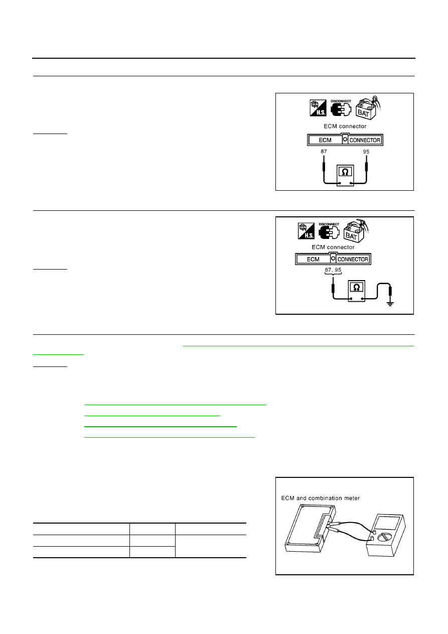
Component Inspection
EKS00AR3
ECM / COMBINATION METER INTERNAL CIRCUIT INSPECTION
●
Remove ECM and Combination meter from vehicle.
●
Check resistance between ECM terminals 95 and 87.
●
Check resistance between Combination meter terminals 43 and
44.
95(L) – 87(R)
: Continuity should not exist.
MKIB0609E
95(L) – ground
: Continuity should not exist.
87(R) – ground
: Continuity should not exist.
MKIB0610E
Unit
Terminal
Resistance value (
Ω
)
ECM
95 – 87
Approx. 108 - 132
Combination meter
43 – 44
PKIA0830E