Nissan Primera P12. Manual - part 535


  Главная      Nissan     Nissan Primera P12 - Service Manual


поиск по сайту            


содержание   ..  533  534  535  536   ..


Nissan Primera P12. Manual - part 535


LAN-52

[CAN]

CAN SYSTEM (TYPE 23)

Smart Entrance Control Unit Circuit Check

EKS00AQZ

1.

CHECK CONNECTOR

1.

Turn ignition switch OFF.

2.

Disconnect the negative battery cable.

3.

Check terminals and connector of smart entrance control unit for damage, bend and loose connec-
tion.(control unit side and harness side)

OK or NG

OK

>> GO TO 2.

NG

>> Repair terminal or connector.

2.

CHECK HARNESS FOR OPEN CIRCUIT

1.

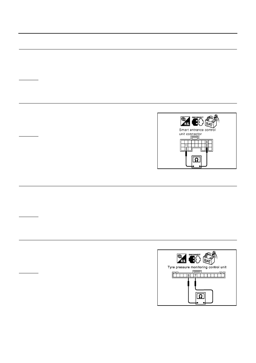
Disconnect smart entrance control unit connector.

2.

Check resistance between smart entrance control unit harness
connector M41 terminals 8(L) and 11(R).

OK or NG

OK

>> Replace smart entrance control unit.

NG

>> Repair harness between Data link connector and smart

entrance control unit.

Tyre Pressure Monitoring Control Unit Circuit Check

EKS00AR0

1.

CHECK CONNECTOR

1.

Turn ignition switch OFF.

2.

Disconnect the negative battery cable.

3.

Check terminals and connector of tyre pressure monitoring control unit for damage, bend and loose con-
nection.(control unit side and harness side)

OK or NG

OK

>> GO TO 2.

NG

>> Repair terminal or connector.

2.

CHECK HARNESS FOR OPEN CIRCUIT

1.

Disconnect tyre pressure monitoring control unit connector.

2.

Check resistance between tyre pressure monitoring control unit
harness connector M96 terminals 7(L) and 5(R).

OK or NG

OK

>> Replace tyre pressure monitoring control unit.

NG

>> Repair harness between smart entrance control unit and

tyre pressure monitoring control unit.

8(L) – 11(R)

: Approx. 54 – 66

PKIA0820E

7(L) – 5(R)

: Approx. 54 – 66

PKIA0863E

CAN SYSTEM (TYPE 23)

LAN-53

[CAN]

C

D

E

F

G

H

I

J

L

M

A

B

LAN

Combination Meter Circuit Check

EKS00AR1

1.

CHECK CONNECTOR

1.

Turn ignition switch OFF.

2.

Disconnect the negative battery cable.

3.

Check terminals and connector of combination meter for damage, bend and loose connection.(meter side
and harness side)

OK or NG

OK

>> GO TO 2.

NG

>> Repair terminal or connector.

2.

CHECK HARNESS FOR OPEN CIRCUIT

1.

Disconnect combination meter connector.

2.

Check resistance between combination meter harness connec-
tor M37 terminals 43(L) and 44(R).

OK or NG

OK

>> Replace combination meter.

NG

>> Repair harness between tyre pressure monitoring con-

trol unit and combination meter.

CAN Communication Circuit Check

EKS00AR2

1.

CHECK CONNECTOR

1.

Turn ignition switch OFF.

2.

Disconnect the negative battery cable.

3.

Check following terminals and connector for damage, bend and loose connection. (meter side, control unit
side, control module side and harness side)

Combination meter

Tyre pressure monitoring control unit

Smart entrance control unit

ABS actuator and electric unit (control unit)

ECM

Between ABS actuator and electric unit (control unit) and ECM

OK or NG

OK

>> GO TO 2.

NG

>> Repair terminal or connector.

43(L) – 44(R)

: Approx. 108 – 132

PKIA0823E

LAN-54

[CAN]

CAN SYSTEM (TYPE 23)

2.

CHECK HARNESS FOR SHORT CIRCUIT

1.

Disconnect the following connectors.

Combination meter connector

Tyre pressure monitoring control unit connector

Smart entrance control unit connector

Harness connector M89

Harness connector M77

2.

Check continuity between Data link connector M10 terminals 6
(L) and 3(R).

OK or NG

OK

>> GO TO 3.

NG

>>

Repair harness between tyre pressure monitoring
control unit and combination meter.

Repair harness between smart entrance control unit
and tyre pressure monitoring control unit.

Repair harness between Data link connector and
smart entrance control unit.

Repair harness between harness connector M89 and harness connector M77.

3.

CHECK HARNESS FOR SHORT CIRCUIT

Check continuity between Data link connector M10 terminals 6 (L),
3(R) and ground.

OK or NG

OK

>> GO TO 4.

NG

>>

Repair harness between tyre pressure monitoring
control unit and combination meter.

Repair harness between smart entrance control unit
and tyre pressure monitoring control unit.

Repair harness between Data link connector and smart entrance control unit.

Repair harness between harness connector M89 and harness connector M77.

4.

CHECK HARNESS FOR SHORT CIRCUIT

1.

Disconnect harness connector B107.

2.

Check the following.

Continuity between harness connector B102 terminals 1 (L) and
8(G).(Sedan models)

Continuity between harness connector B102 terminals 1 (L) and
8(R).(Wagon models)

OK or NG

OK

>> GO TO 5.

NG

>> Repair harness between harness connector B102 and harness connector B107.

6(L) – 3(R)

: Continuity should not exist.

PKIA0824E

6(L) – ground

: Continuity should not exist.

3(R) – ground

: Continuity should not exist.

PKIA0825E

1(L) – 8(G) (Sedan
models)

: Continuity should not exist.

1(L) – 8(R) (Wagon
models)

: Continuity should not exist.

PKIA0832E

CAN SYSTEM (TYPE 23)

LAN-55

[CAN]

C

D

E

F

G

H

I

J

L

M

A

B

LAN

5.

CHECK HARNESS FOR SHORT CIRCUIT

1.

Check the following.

Continuity between harness connector B102 terminals 1 (L),
8(G) and ground.(Sedan models)

Continuity between harness connector B102 terminals 1 (L),
8(R) and ground.(Wagon models)

OK or NG

OK

>> GO TO 6.

NG

>> Repair harness between harness connector B102 and harness connector B107.

6.

CHECK HARNESS FOR SHORT CIRCUIT

1.

Disconnect ABS actuator and electric unit (control unit) connector.

2.

Check continuity between ABS actuator and electric unit (control
unit) harness connector E64 terminals 26 (L) and 15(R).

OK or NG

OK

>> GO TO 7.

NG

>> Repair harness between ABS actuator and electric unit

(control unit) and harness connector E120.

7.

CHECK HARNESS FOR SHORT CIRCUIT

Check continuity between ABS actuator and electric unit (control
unit) harness connector E64 terminals 26 (L), 15 (R) and ground.

OK or NG

OK

>> GO TO 8.

NG

>> Repair harness between ABS actuator and electric unit

(control unit) and harness connector E120.

1(L) – ground (Sedan
models)

: Continuity should not exist.

8(G) – ground
(Sedan models)

: Continuity should not exist.

1(L) – ground
(Wagon models)

: Continuity should not exist.

8(R) – ground
(Wagon models)

: Continuity should not exist.

PKIA0833E

26(L) – 15(R)

: Continuity should not exist.

PKIA0831E

26(L) – ground

: Continuity should not exist.

15(R) – ground

: Continuity should not exist.

PKIA0834E


содержание   ..  533  534  535  536   ..