Nissan Primera P12. Manual - part 505


  Главная      Nissan     Nissan Primera P12 - Service Manual


поиск по сайту            


содержание   ..  503  504  505  506   ..


Nissan Primera P12. Manual - part 505


GW-16

REAR WINDOW DEFOGGER

REAR WINDOW DEFOGGER

PFP:25350

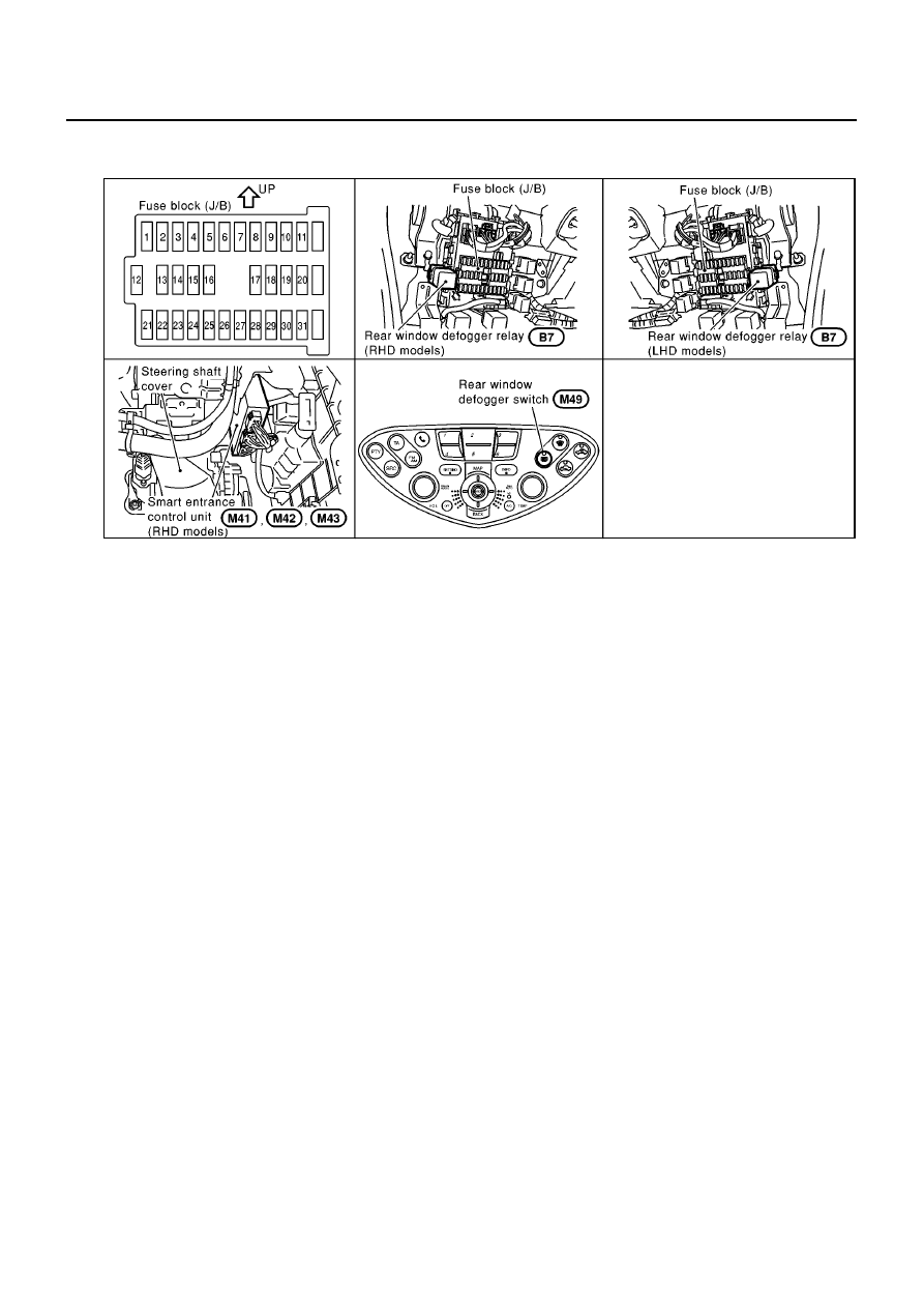
Component Parts and Harness Connector Location

EIS005JW

System Description

EIS0060O

The rear window defogger system is controlled by smart entrance control unit.
The rear window defogger operates only for approximately 15 minutes.
Power is supplied at all times

through 20A fuse [No. 7, located in the fuse block (J/B)]

to rear window defogger relay terminal 3.

through 10A fuse [No. 12, located in the fuse block (J/B)]

to smart entrance control unit terminal 56.

With the ignition switch in the ON or START position, power is supplied

through 10A fuse [No. 10, located in the fuse block (J/B)]

to rear defogger relay terminal 1 and

to smart entrance control unit terminal 29.

through 10A fuse [No. 23, located in the fuse block (J/B)]

to rear window defogger relay terminal 6 (with door mirror defogger).

through 10A fuse [No.1, located in the fuse block (J/B)]

to multifunction switch terminal 6.

Ground is supplied

to smart entrance control unit terminal 53

through body grounds M16, M50, M70 and F115.

to multifunction switch terminal 1

through body grounds M16, M50, M70 and F115.

When the multifunction switch (rear window defogger switch) is turned ON, ground is supplied

to smart entrance control unit terminal 22

through multifunction switch (rear window defogger switch) terminal 9.

Terminal 31 of the smart entrance control unit then supplies ground to the rear window defogger relay terminal
2.
With power and ground supplied, the rear window defogger relay is energized.
Power is supplied

through terminals 5 and 7 of the rear window defogger relay

to the rear window defogger and door mirror defogger.

MIIA0111E

REAR WINDOW DEFOGGER

GW-17

C

D

E

F

G

H

J

K

L

M

A

B

GW

The rear window defogger has an independent ground.
With power and ground supplied, the rear window defogger filaments heat and defog the rear window.
When the system is activated, the rear window defogger indicator illuminates in the multifunction switch (rear
window defogger switch).
Power is supplied

through rear window defogger relay terminal 5

to multifunction switch (rear window defogger switch) terminal 10.

CAN Communication

EIS0060P

SYSTEM DESCRIPTION

CAN (Controller Area Network) is a serial communication line for real time application. It is an on-vehicle mul-
tiplex communication line with high data communication speed and excellent error detection ability. Many elec-
tronic control units are equipped onto a vehicle, and each control unit shares information and links with other
control units during operation (not independent). In CAN communication, control units are connected with 2
communication lines (CAN H line, CAN L line) allowing a high rate of information transmission with less wiring.
Each control unit transmits/receives data but selectively reads required data only.

CAN COMMUNICATION UNIT

×

:Applicable

Body type

Sedan/Wagon/Hatch back

Axle

2WD

Engine

YD22DDTi

F9Q

Transmission

M/T

Brake control

ESP

ABS

ESP

ABS

CAN communication unit

ECM

×

×

×

×

×

×

×

×

ESP/TCS/ABS control unit

×

×

×

×

ABS actuator and electric
unit (control unit)

×

×

×

×

Data link connector

×

×

×

×

×

×

×

×

Tyre pressure monitoring
control unit

×

×

×

×

Steering angle sensor

×

×

×

×

Smart entrance control unit

×

×

×

×

×

×

×

×

Combination meter

×

×

×

×

×

×

×

×

Can communication type

GW-18, "TYPE

21,TYPE22/TYPE29,

TYPE30"

GW-19, "TYPE

23,TYPE24/TYPE31,

TYPE32"

GW-20, "TYPE 25/

TYPE26"

GW-21, "TYPE 27/
TYPE28"

GW-18

REAR WINDOW DEFOGGER

TYPE 21,TYPE22/TYPE29, TYPE30
System diagram

LHD models (Type21, Type22)

RHD models (Type29, Type30)

Input/output signal chart

T: Transmit R: Receive

SKIA1524E

SKIA1538E

Signals

ECM

ESP/ TCS /

ABS control

unit

Steering

angle sensor

Smart

entrance

control unit

Tyre pres-

sure monitor-

ing control

unit

Combination

meter

Engine speed signal

T

R

R

Accelerator pedal position signal

T

R

Steering angle sensor signal

R

T

Air conditioner switch signal

R

T

MI signal

T

R

Glow indicator lamp signal

T

R

Engine coolant temperature signal

T

R

Fuel consumption signal

T

R

Vehicle speed signal

T

R

R

R

T

Seat belt reminder signal

R

T

Lighting switch position signal

T

R

Flashing indicator signal

T

R

Engine cooling fan speed signal

T

R

Child lock indicator signal

T

R

Door switches state signal

T

R

A/C compressor signal

T

R

Tyre pressure signal

T

R

REAR WINDOW DEFOGGER

GW-19

C

D

E

F

G

H

J

K

L

M

A

B

GW

TYPE 23,TYPE24/TYPE31, TYPE32
System diagram

LHD models (Type23, Type24)

RHD models (Type31, Type32)

Input/output signal chart

T: Transmit R: Receive

SKIA1525E

SKIA1539E

Signals

ECM

ABS actuator

and electric

unit (control

unit)

Smart entrance

control unit

Tyre pressure

monitoring

control unit

Combination

meter

Engine speed signal

T

R

Air conditioner switch signal

R

T

MI signal

T

R

Glow indicator lamp signal

*1

T

R

Engine coolant temperature signal

T

R

Fuel consumption signal

T

R

Vehicle speed signal

T

R

R

R

T

Seat belt reminder signal

R

T

Lighting switch position signal

T

R

Flashing indicator signal

T

R

Engine cooling fan speed signal

T

R

Child lock indicator signal

T

R

Door switches state signal

T

R

A/C compressor signal

T

R

Tyre pressure signal

T

R


содержание   ..  503  504  505  506   ..