Nissan Primera P12. Manual - part 466


  Главная      Nissan     Nissan Primera P12 - Service Manual


поиск по сайту            


содержание   ..  464  465  466  467   ..


Nissan Primera P12. Manual - part 466


EM-210

[F9Q]

OVERHAUL

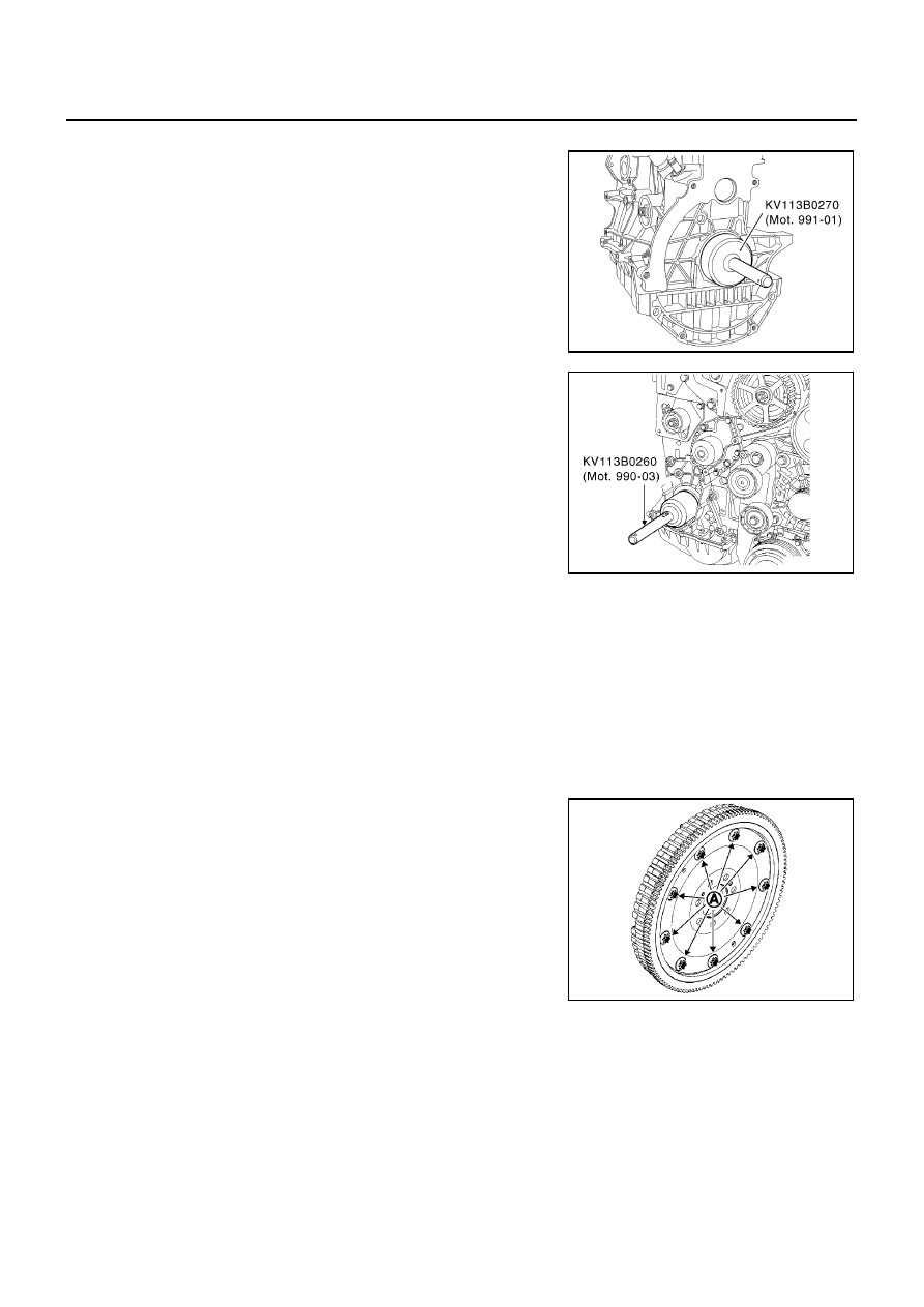
Installation of Old Type Crankshaft Seal

For flywheel side, use Tool KV113B0270 (Mot. 991-01).

For timing side, use Tool KV113B0260 (Mot. 990-03).

INSTALLATION OF FLYWHEEL

1.

Lock the flywheel with Tool KV113B0060 (Mot. 582-01) or KV113B0410 (Mot. 1677) depending on the cyl-
inder block (large or small side).

2.

Install the flywheel, tightening the new bolts to a torque of 30 N·m (3.1 kg-m, 22 ft-lb), then tighten to an
angle of 56

°±

6

°

for a double mass flywheel 55 N·m (5.6kg-m, 41ft-lb) for a standard flywheel.

CAUTION:

Use an angle wrench (special service tool) to check tightening angle. Do not make judgment by
visual inspection.

3.

Flexible flywheel:

NOTE:
Under no circumstances should bolts (A) be removed.

MBIB0836E

MBIB0837E

MBIB0759E

OVERHAUL

EM-211

[F9Q]

C

D

E

F

G

H

I

J

K

L

M

A

EM

NOTE:
Install the flywheel without its shim (B) is strictly prohibited, the
shim is usually joined to flexplate (C) (see the diagram opposite)
by two pins (D).

4.

It is essential to replace the flywheel mounting bolts.

Tighten the engine flywheel bolts in the numerical order as
shown.

5.

Proceed in the reverse order to removal.

6.

Install the clutch.

7.

Remove Tool KV113B0060 (Mot. 582-01) or KV113B0410 (Mot.
1677).

Installation of Lower Engine Assembly

1.

Install the oil separator installed with a new seal.

2.

Install the oil cooler. Refer to

LU-20, "OIL COOLER"

.

3.

Install the oil filter. Refer to

LU-18, "OIL FILTER"

.

4.

Install the oil pressure switch.

5.

Install the oil level sensor.

6.

Install the water pipe.

7.

Install the water pump inlet pipe installed with a new seal.

MBIB0838E

: 65 N·m (6.6 kg-m, 48 ft-lb)

MBIB0839E

: 20 N·m (2.0 kg-m, 15 ft-lb)

MBIB0757E

: 10 N·m (1.0 kg-m, 87 in-lb)

: 38 N·m (3.9 kg-m, 28 ft-lb)

: 30 N·m (3.1 kg-m, 22 ft-lb)

: 40 N·m (4.1 kg-m, 30 ft-lb)

: 10 N·m (1.0 kg-m, 87 in-lb)

MBIB0756E

EM-212

[F9Q]

OVERHAUL

8.

Install the alternator bracket.

9.

Install the A/C compressor.

10. Install the alternator.

: 50 N·m (5.1 kg-m, 37 ft-lb)

MBIB0755E

: 25 N·m (2.6 kg-m, 18 ft-lb)

MBIB0754E

: 25 N·m (2.6 kg-m, 18 ft-lb)

MBIB0753E

OVERHAUL

EM-213

[F9Q]

C

D

E

F

G

H

I

J

K

L

M

A

EM

11. Install the power steering pump.

12. Install the idler pulley (1).

Assembly of Upper Engine

EBS00SBR

INSTALLATION OF CYLINDER HEAD

1.

Position the pistons at mid-stroke.

2.

Install the cylinder head gasket using the centring sockets of the cylinder block.

3.

Tighten the cylinder head. Refer to

EM-162, "INSTALLATION"

.

TIMING ADJUSTMENT

1.

Make sure that Tool KV113B0280 (Mot. 1054) is in place.

2.

The notch (4) in the crankshaft must be located in the middle of
the two grooves (2) on the front cover. The mark (3) of the
crankshaft timing sprocket should be moved to the left by one
notch of the engine vertical axis.

3.

Check that the tensioner is securely positioned on the pin (1).

4.

Install the timing belt, aligning the mark on the belt with the
marks on the camshaft and crankshaft sprocket.

: 25 N·m (2.6 kg-m, 18 ft-lb)

: 25 N·m (2.6 kg-m, 18 ft-lb)

MBIB0752E

MBIB0840E

MBIB0841E


содержание   ..  464  465  466  467   ..