Nissan Primera P12. Manual - part 437


  Главная      Nissan     Nissan Primera P12 - Service Manual


поиск по сайту            


содержание   ..  435  436  437  438   ..


Nissan Primera P12. Manual - part 437


EM-94

[YD]

CYLINDER BLOCK

CAUTION:

Apply new engine oil to parts marked in illustration before installation.

DISASSEMBLY

1.

Remove engine assembly from the vehicle, then separate engine and transaxle. Refer to

EM-89,

"ENGINE ASSEMBLY"

.

2.

Remove clutch cover and disk. Refer to

CL-15, "CLUTCH DISC, CLUTCH COVER AND FLYWHEEL"

.

3.

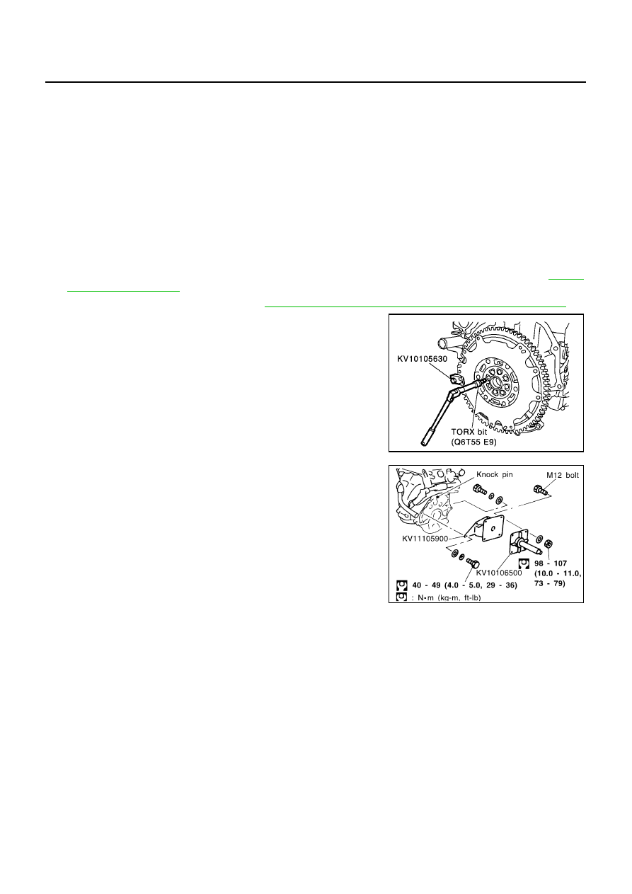
Install engine to engine stand as follows.

a.

Remove flywheel.

b.

Secure ring gear with ring gear stopper, then loosen mounting
bolts with TORX bit (size: Q6T55 E9, Commercial Service Tools)
and remove them. As an alternative method hold the crankshaft
pulley with a pulley holder (SST) to remove the flywheel.

CAUTION:

Do not disassemble flywheel.

c.

Install engine sub-attachment to the rear side of cylinder block.

Align knock pins on cylinder block with pin holes on attach-
ment to install.

NOTE:
Installation bolts are part of engine sub-attachment.

d.

Install engine attachment.

NOTE:
Use commercially available M12 (0.47 in) mounting bolts and
nuts (4 sets) with strength grade of 9T (minimum).

1.

Rear oil seal retainer

2.

Oil pressure switch

3.

Coppet washer

4.

Oil jet relief valve

5.

Cylinder block

6.

Top ring

7.

Second ring

8.

Oil ring

9.

Oil jet

10.

Piston pin

11.

Snap ring

12.

Piston

13.

Main bearing

14.

Thrust bearing

15.

Connecting rod

16.

Key

17.

Connecting rod bearing

18.

Connecting rod cap

19.

Connecting rod nut

20.

Main bearing

21.

Crankshaft

22.

Main bearing cap

23.

Pilot bush

24.

Flywheel

25.

Drain plug

26.

Rear oil seal

SBIA0199E

JEM192G

CYLINDER BLOCK

EM-95

[YD]

C

D

E

F

G

H

I

J

K

L

M

A

EM

e.

Hoist engine and install it to the engine stand.

NOTE:
It is possible to set engine sub-attachment and engine attach-
ment to engine stand at first, then install engine later.

Commercial engine stand can be used.

NOTE:
The figure shows an example of general-purpose engine stand
that can hold mating surface of transmission with drive plate and
rear plate removed.

4.

Drain engine oil and coolant from inside engine.

5.

Remove the following parts and related parts. (Only major parts are listed.)

Intake manifold (Refer to

EM-19, "Removal and Installation"

.)

Exhaust manifold and turbocharger (Refer to

EM-23, "Removal and Installation"

.)

Rocker cover (Refer to

EM-52, "Removal and Installation"

).

Injection tube and fuel injector (Refer to

EM-39, "Removal and Installation"

.)

Oil pan and oil strainer (Refer to

EM-29, "Removal and Installation"

.)

Water pump (Refer to

CO-17, "Removal and Installation"

.)

Thermostat and water piping (Refer to

CO-19, "Removal and Installation"

.)

Vacuum pump (Refer to

EM-35, "Removal and Installation"

.)

Secondary timing chain (Refer to

EM-63, "Removal and Installation"

)

Primary timing chain (Refer to

EM-68, "Removal and Installation"

.)

Fuel pump (Refer to

EM-42, "Removal and Installation"

.)

Camshaft (Refer to

EM-54, "Removal and Installation"

.)

Cylinder head (Refer to

EM-79, "Removal and Installation"

.)

Oil cooler (Refer to

LU-12, "Removal and Installation"

.)

Accessory, accessory bracket and mount brackets

6.

Remove fuel pump bracket.

JEM193G

PBIC0085E

EM-96

[YD]

CYLINDER BLOCK

7.

If they need to be replaced, replace pilot bushing.

Using pilot bushing puller, remove the bushing from rear edge
of crankshaft.

8.

Remove rear oil seal retainer.

Insert a flat-bladed screwdriver between main bearing cap and rear oil seal retainer to remove retainer.

9.

Remove rear oil seal from rear oil seal retainer.

Punch out with a flat-bladed screwdriver.

Be careful not to damage rear oil seal retainer.

10. Remove piston and connecting rod assembly.

Before removing piston and connecting rod assembly, check
connecting rod side clearance.
Refer to

EM-106, "CONNECTING ROD SIDE CLEARANCE"

.

a.

Move crankshaft pin to be removed to approximately BDC.

b.

Remove connecting rod caps.

c.

Using the grip of a hammer, press the piston and connecting rod
assembly out to cylinder head side.

CAUTION:

When removing the piston and connecting rod assembly,
prevent the big end of the connecting rod from interfering
with the oil jet.

11. Remove connecting rod bearings from connecting rods and

caps.

Keep them by cylinder to avoid confusion.

12. Remove piston rings from pistons using piston ring expander.

CAUTION:

When removing, prevent pistons from being damaged.

Do not expand piston rings excessively. This may dam-
age the piston rings.

SEM500G

JEM195G

FEM086

JEM196G

CYLINDER BLOCK

EM-97

[YD]

C

D

E

F

G

H

I

J

K

L

M

A

EM

13. Remove pistons from connecting rods.

a.

Using long nose pliers, remove snap rings.

b.

Using industrial dryer, heat pistons up to 60 to 80

°

C (140 to

176

°

F).

c.

Using rod with outer diameter of 26 mm (1.02 in), press piston
pins out.

14. Remove main bearing cap bolts.

With a TORX socket (size: E-14,Commercial Service Tool),
loosen main bearing cap bolts in several stages in the reverse
order of that shown in the figure and remove them.

Before loosening main bearing cap bolts, measure crankshaft
side clearance. Refer to

EM-105, "CRANKSHAFT SIDE

CLEARANCE"

.

15. Remove main bearing caps.

Using main bearing cap bolts, remove by rocking bearing cap
back and forth.

16. Remove crankshaft.

17. Remove main bearings and thrust bearings from cylinder block

and main bearing caps.

Check the correct installation locations of removed parts.
Store them so they do not get mixed up.

18. Remove oil jet.

19. Remove oil jet relief valve.

JEM197G

PBIC0089E

EMM0072D

JEM200G

JEM201G


содержание   ..  435  436  437  438   ..