Nissan Primera P12. Manual - part 436


  Главная      Nissan     Nissan Primera P12 - Service Manual


поиск по сайту            


содержание   ..  434  435  436  437   ..


Nissan Primera P12. Manual - part 436


EM-90

[YD]

ENGINE ASSEMBLY

2.

Drain coolant from radiator drain plug.

3.

Remove the following parts.

LH/RH undercover

LH/RH front wheel

Battery

Engine cover

Auxiliary drive belt; Refer to

EM-14, "Removal and Installation"

.

Air duct and air cleaner case assembly; Refer to

EM-15, "Removal and Installation"

.

Alternator

Radiator and radiator fan assembly; Refer to

CO-10, "Removal and Installation"

.

4.

Disconnect engine room harness from the engine side and set it aside for easier work.

5.

Disconnect all the body-side vacuum hoses and air hoses at engine side.

Engine room LH

6.

Disconnect fuel feed and return hoses, and plug it to prevent fuel from draining.

7.

Disconnect heater hose, and install plug it to prevent engine coolant from draining.

8.

Remove clutch operating cylinder from transaxle, and move it aside.

9.

Disconnect shift cable from transaxle.

Engine room RH

10. Remove engine coolant reservoir tank.

11. Remove air conditioner compressor with piping connected from engine. Temporarily secure it on body

with a rope to avoid putting load on it.

Vehicle underbody
12. Remove exhaust front tube.

13. Remove steering shaft from steering gear.

14. Disconnect power steering fluid cooler piping at a point between body and engine.

15. Remove ABS sensor from brake caliper.

16. Remove brake caliper with piping connected from steering knuckle. Temporarily secure it on body with a

rope to avoid load on it.

17. Remove LH/RH suspension from steering knuckle under strut.
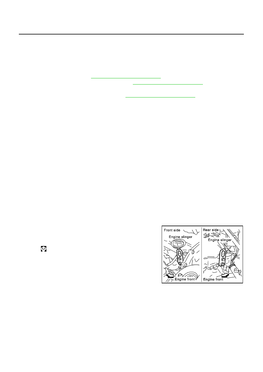
Removal

18. Install engine slingers into front right of cylinder head and rear

left of cylinder head.

19. Lift with hoist and secure the engine in position.

Slinger bolts:

: 30 - 37 N·m (3.0 - 3.8 kg-m, 22 - 27 ft-lb)

SBIA0191E

ENGINE ASSEMBLY

EM-91

[YD]

C

D

E

F

G

H

I

J

K

L

M

A

EM

Use a manual lift table caddy or equivalently rigid tool such as
a jack or trestle. Securely support bottom of engine and
transaxle, and simultaneously adjust hoist tension.

CAUTION:

Put a piece of wood or something similar as the support-
ing surface, secure a completely stable condition.

20. Remove RH engine mounting insulator.
21. Pull LH engine mounting through-bolt out.

22. Remove mounting bolts at front end of center member.

23. Remove front suspension member mounting bolts and nuts.

24. Remove engine, transaxle assembly with suspension member

from vehicle downward by carefully operating supporting tools.

CAUTION:

During the operation, make sure that no part interferes
with body side.

Before and during this lifting, always check if any har-
nesses are left connected.

During the removal operation, always be careful to pre-
vent vehicle from falling off the lift due to changes in the
center of gravity.

If necessary, support vehicle by setting a jack or equivalent tool at the rear.

25. Remove power steering pump with piping connected from engine. Move it aside on suspension member.

26. Remove front engine mounting and rear engine mounting through-bolts to remove suspension member.

27. Remove starter motor.

28. Separate engine and transaxle.

INSTALLATION

Install in the reverse order of removal.

Do not allow oil to get on mounting insulator. Be careful not to damage mounting insulator.

When installation directions are specified, install parts according to the direction marks on them referring
to components illustration.

Make sure that each mounting insulator is seated properly, and tighten mounting bolts and nuts.

INSPECTION AFTER INSTALLATION

Before starting engine check the levels of coolant, lubrications and working oils. If less than required
quantity, fill to the specified level.

Before starting engine, bleed air from fuel piping. Refer to

FL-5, "Air Bleeding"

.

Run engine to check for unusual noise and vibration.

Warm up engine thoroughly to make sure there is no leakage of coolant, lubricants, working oil, fuel and
exhaust gas.

PBIC0734E

MBIA0087E

PBIC0748E

EM-92

[YD]

ENGINE ASSEMBLY

Bleed air from passages in pipes and tubes of applicable lines.

CYLINDER BLOCK

EM-93

[YD]

C

D

E

F

G

H

I

J

K

L

M

A

EM

CYLINDER BLOCK

PFP:11010

Disassembly and Assembly

EBS00SO4

MBIA0015E


содержание   ..  434  435  436  437   ..