содержание .. 295 296 297 298 ..
Nissan Primera P12. Manual - part 297
ON BOARD DIAGNOSTIC (OBD) SYSTEM
EC-373
[YD (WITHOUT EURO-OBD)]
C
D
E
F
G
H
I
J
K
L
M
A
EC
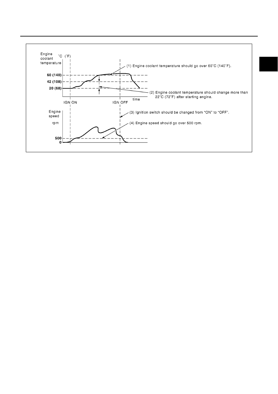
Driving Pattern A
●
The A counter will be cleared when the malfunction is detected regardless of (1) - (4).
●
The A counter will be counted up when (1) - (4) are satisfied without the same malfunction.
●
The DTC will not be displayed after the A counter reaches 40.
MBIB0923E