Nissan Primera P12. Manual - part 295


  Главная      Nissan     Nissan Primera P12 - Service Manual


поиск по сайту            


содержание   ..  293  294  295  296   ..


Nissan Primera P12. Manual - part 295


ENGINE CONTROL SYSTEM

EC-365

[YD (WITHOUT EURO-OBD)]

C

D

E

F

G

H

I

J

K

L

M

A

EC

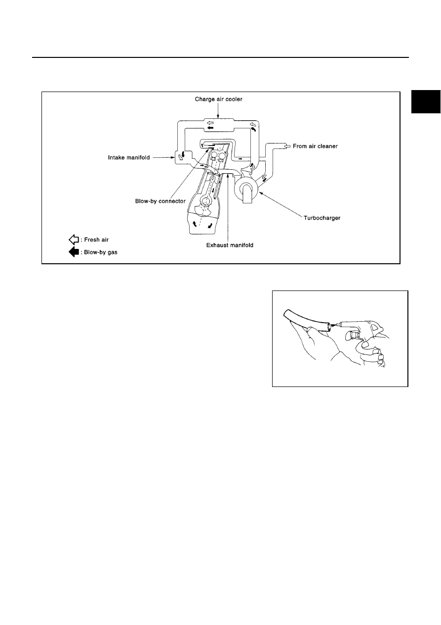
Crankcase Ventilation System

EBS0152Z

DESCRIPTION

In this system, blow-by gas is sucked into the air duct after oil separation by oil separator in the rocker cover.

INSPECTION
Ventilation Hose

1.

Check hoses and hose connections for leaks.

2.

Disconnect all hoses and clean with compressed air. If any hose
cannot be freed of obstructions, replace.

CAN Communication

EBS01530

SYSTEM DESCRIPTION

CAN (Controller Area Network) is a serial communication line for real time application. It is an on-vehicle mul-
tiplex communication line with high data communication speed and excellent error detection ability. Many elec-
tronic control units are equipped onto a vehicle, and each control unit shares information and links with other
control units during operation (not independent). In CAN communication, control units are connected with 2
communication lines (CAN H line, CAN L line) allowing a high rate of information transmission with less wiring.
Each control unit transmits/receives data but selectively reads required data only.

PBIB0590E

SEC692

EC-366

[YD (WITHOUT EURO-OBD)]

ENGINE CONTROL SYSTEM

MODELS WITH ESP
System Diagram

LHD models

RHD models

Input/Output Signal Chart

T: Transmit R: Receive

SKIA1524E

SKIA1538E

Signals

ECM

ESP/ TCS /

ABS control

unit

Steering

angle sensor

Smart

entrance

control unit

Tyre pres-

sure monitor-

ing control

unit

Combination

meter

Engine speed signal

T

R

R

Accelerator pedal position signal

T

R

Steering angle sensor signal

R

T

Air conditioner switch signal

R

T

MI signal

T

R

Glow indicator lamp signal

T

R

Engine coolant temperature signal

T

R

Fuel consumption signal

T

R

Vehicle speed signal

T

R

R

R

T

Seat belt reminder signal

R

T

Lighting switch position signal

T

R

Flashing indicator signal

T

R

Engine cooling fan speed signal

T

R

Child lock indicator signal

T

R

Door switches state signal

T

R

A/C compressor signal

T

R

Tyre pressure signal

T

R

ASCD SET lamp signal

T

R

ASCD CRUISE lamp signal

T

R

ENGINE CONTROL SYSTEM

EC-367

[YD (WITHOUT EURO-OBD)]

C

D

E

F

G

H

I

J

K

L

M

A

EC

MODELS WITHOUT ESP
System Diagram

LHD models

RHD models

Input/Output Signal Chart

T: Transmit R: Receive

SKIA1525E

SKIA1539E

Signals

ECM

ABS actuator

and electric

unit (control

unit)

Smart entrance

control unit

Tyre pressure

monitoring

control unit

Combination

meter

Engine speed signal

T

R

Air conditioner switch signal

R

T

MI signal

T

R

Glow indicator lamp signal

T

R

Engine coolant temperature signal

T

R

Fuel consumption signal

T

R

Vehicle speed signal

T

R

R

R

T

Seat belt reminder signal

R

T

Lighting switch position signal

T

R

Flashing indicator signal

T

R

Engine cooling fan speed signal

T

R

Child lock indicator signal

T

R

Door switches state signal

T

R

A/C compressor signal

T

R

Tyre pressure signal

T

R

ASCD SET lamp signal

T

R

ASCD CRUISE lamp signal

T

R

EC-368

[YD (WITHOUT EURO-OBD)]

BASIC SERVICE PROCEDURE

BASIC SERVICE PROCEDURE

PFP:00018

Fuel Filter

EBS01531

DESCRIPTION

A water draining cock is on the lower side and a priming pump for bleeding air is on the upper side.

AIR BLEEDING

Pump the priming pump to bleed air.

When air is bled completely, the pumping of the priming pump
suddenly becomes heavy. Stop the operation at that time.

If it is difficult to bleed air by the pumping of the priming pump
(the pumping of the priming pump does not become heavy), dis-
connect the fuel supply hose between the fuel filter and the fuel
gallery. Then, perform the operation described above, and make
sure that fuel comes out. (Use a pan, etc. so as not to spill fuel.
Do not let fuel get on engine and other parts.) After that, connect
the hose, then bleed air again.

Start engine and let it idle for at least 1 minute after performing
air bleeding.

WATER DRAINING

1.

Remove the fuel filter, filter bracket, protector assembly from the dash panel as follows.

a.

Remove the air cleaner case (upper), air duct assembly, and vacuum hose for brake booster (between the
vacuum pump and vacuum pipe).

CAUTION:

After the duct is removed, cover the opening with gum tape, etc. to prevent foreign object from
getting into the engine during the operation.

b.

Remove the mounting nuts on the dash panel, then remove the fuel filter, filter bracket, and protector
assembly from the dash panel.

It is not necessary to disconnect the fuel hose.

2.

Using a tool such as a pliers, loosen the water draining cock at
the bottom of the fuel filter.
Loosening drain cock four to five turns causes water to
start draining.
Do not remove drain cock by loosening it excessively.
If water dose not drain properly, move the priming up and down.

CAUTION:

When the water is drained, the fuel is also drained. Use a
pan, etc. to avoid fuel adherence to the rubber parts such as
the engine mount insulator.
Do not over-tighten the water draining cock. This will dam-
age the cock thread, resulting in water or fuel leak.

3.

Bleed air of the fuel filter. Refer to

EC-368, "AIR BLEEDING"

.

4.

Start the engine.

Fuel Pump Learning Value Clearing

EBS01532

DESCRIPTION

In order to always keep optimum fuel pressure in fuel rail, the ECM controls fuel pump in high precision with
monitoring the signal of fuel rail pressure sensor.
Accordingly, the ECM always learns characteristic value of fuel pump. Fuel Pump Learning Value Clearing is
an operating to clear the value of the fuel pump learning.
It must be performed after the fuel pump is changed. When the ECM is replaced with brand new one, the Fuel
Pump Learning Value Clearing is not necessary to be performed. If the ECM to be replaced has the possibility
of learning the characteristic value of fuel pump, the Fuel Pump Learning Value Clearing is necessary to be
performed after the ECM has been replaced.

OPERATION PROCEDURE

NOTE:
Remove fuel pump without starting engine after performing Fuel Pump Learning Value Clearing.

MBIB0074E

SMA825B


содержание   ..  293  294  295  296   ..