содержание .. 292 293 294 295 ..
Nissan Primera P12. Manual - part 294
ENGINE CONTROL SYSTEM
EC-361
[YD (WITHOUT EURO-OBD)]
C
D
E
F
G
H
I
J
K
L
M
A
EC
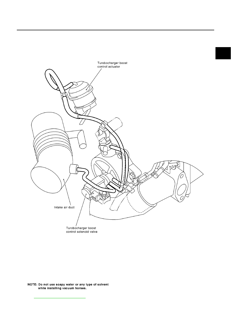
Vacuum Hose Drawing
EBS0152T
Refer to
for Vacuum Control System.
MBIB0609E
|
|
|
содержание .. 292 293 294 295 ..
ENGINE CONTROL SYSTEM EC-361 [YD (WITHOUT EURO-OBD)] C D E F G H I J K L M A EC Vacuum Hose Drawing EBS0152T Refer to for Vacuum Control System. MBIB0609E |