содержание .. 290 291 292 293 ..
Nissan Primera P12. Manual - part 292
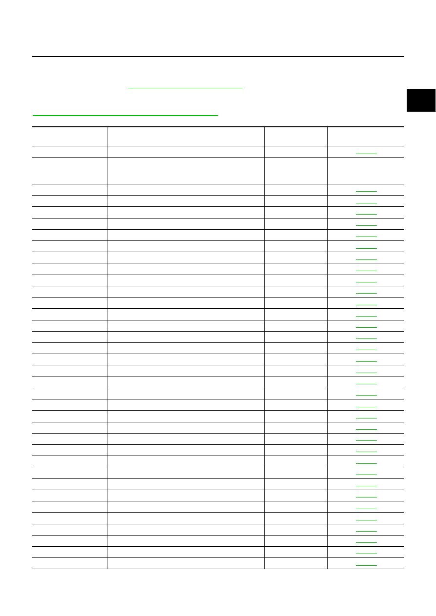
INDEX FOR DTC
EC-353
[YD (WITHOUT EURO-OBD)]
C
D
E
F
G
H
I
J
K
L
M
A
EC
DTC No. Index
EBS0152L
Check if the vehicle is a model with Euro-OBD (E-OBD) system or not by the “Type approval number” on the
identification plate. Refer to
.
NOTE:
If DTC U1000 is displayed with other DTC, first perform the trouble diagnosis for DTC U1000. Refer to
EC-416, "DTC U1000 CAN COMMUNICATION LINE"
.
X: Applicable —: Not applicable
DTC*
Items
(CONSULT-II screen item)
MI lighting up
Reference page
U1000
CAN COMM CIRCUIT
—
P0000
NO DTC IS DETECTED.
FURTHER TESTING
MAY BE REQUIRED.
—
—
P0016
CMP/CKP RELATION
—
P0088
HIGH FUEL PRESS
×
P0089
FUEL PUMP
—
P0093
FUEL LEAK
×
P0102
MAF SEN/CIRCUIT
—
P0103
MAF SEN/CIRCUIT
—
P0112
IAT SEN/CIRCUIT
—
P0113
IAT SEN/CIRCUIT
—
P0117
ECT SEN/CIRCUIT
—
P0118
ECT SEN/CIRCUIT
—
P0122
APP SEN 1/CIRCUIT
—
P0123
APP SEN 1/CIRCUIT
—
P0182
FUEL TEMP SEN/CIRC
—
P0183
FUEL TEMP SEN/CIRC
—
P0192
FRP SEN/CIRC
—
P0193
FRP SEN/CIRC
—
P0200
INJECTOR
×
P0201
CYL1 INJECTOR
—
P0202
CYL2 INJECTOR
—
P0203
CYL3 INJECTOR
—
P0204
CYL4 INJECTOR
—
P0217
ENG OVER TEMP
×
P0222
APP SEN 2/CIRCUIT
—
P0223
APP SEN 2/CIRCUIT
—
P0234
TC SYSTEM
—
P0237
TC BOOST SEN/CIRC
—
P0238
TC BOOST SEN/CIRC
—
P0335
CKP SEN/CIRCUIT
×
P0336
CKP SENSOR
×
P0340
CMP SEN/CIRCUIT
×
P0341
CMP SENSOR
×
P0501
VEHICLE SPEED
—
P0502
VEHICLE SPEED
—
P0503
VEHICLE SPEED
—