Nissan Primera P12. Manual - part 286


  Главная      Nissan     Nissan Primera P12 - Service Manual


поиск по сайту            


содержание   ..  284  285  286  287   ..


Nissan Primera P12. Manual - part 286


BRAKE SWITCH

EC-329

[YD (WITH EURO-OBD)]

C

D

E

F

G

H

I

J

K

L

M

A

EC

9.

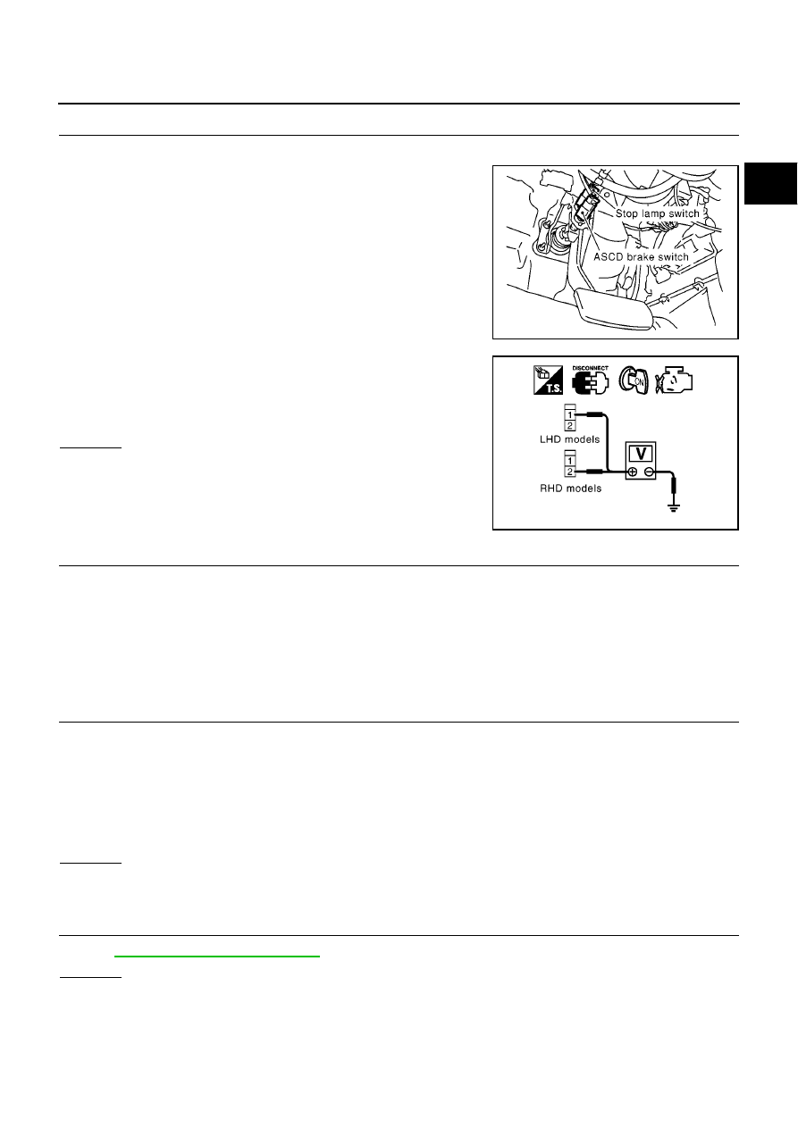
CHECK ASCD BRAKE SWITCH POWER SUPPLY CIRCUIT

1.

Turn ignition switch OFF.

2.

Disconnect ASCD brake switch harness connector.

3.

Turn ignition switch ON.

4.

Check voltage between ASCD brake switch terminal 1 (LHD
models) or 2 (RHD models) and ground with CONSULT-II or
tester.

OK or NG

OK

>> GO TO 11.

NG

>> GO TO 10.

10.

DETECT MALFUNCTIONING PART

Check the following.

Harness connectors F106, M78

Harness for open or short between ASCD brake switch and ECM relay

Harness for open or short between ASCD brake switch and ECM

>> Repair open circuit or short to ground or short to power in harness or connectors.

11.

CHECK ASCD BRAKE SWITCH INPUT SIGNAL CIRCUIT FOR OPEN AND SHORT

1.

Turn ignition switch OFF.

2.

Check harness continuity between ASCD brake switch terminal 2 (LHD models) or 1 (RHD models) and
ASCD brake clutch switch terminal 2.
Refer to Wiring Diagram.

3.

Also check harness for short to ground and short to power.

OK or NG

OK

>> GO TO 12.

NG

>> Repair open circuit or short to ground or short to power in harness or connectors.

12.

CHECK ASCD BRAKE SWITCH

Refer to

EC-330, "Component Inspection"

.

OK or NG

OK

>> GO TO 16.

NG

>> Replace ASCD brake switch.

MBIB0235E

Voltage: Battery voltage

MBIB1082E

Continuity should exist.

EC-330

[YD (WITH EURO-OBD)]

BRAKE SWITCH

13.

CHECK ASCD CLUTCH SWITCH INPUT SIGNAL CIRCUIT FOR OPEN AND SHORT

1.

Turn ignition switch OFF.

2.

Disconnect ECM harness connector.

3.

Check harness continuity between ECM terminal 101 and ASCD clutch switch terminal 1.
Refer to Wiring Diagram.

4.

Also check harness for short to ground or short to power.

OK or NG

OK

>> GO TO 15.

NG

>> GO TO 14.

14.

DETECT MALFUNCTIONING PART

Check the following.

Harness connectors M77, F109

Harness for open or short between ECM and ASCD clutch switch

>> Repair open circuit or short to ground or short to power in harness or connectors.

15.

CHECK ASCD CLUTCH SWITCH

Refer to

EC-330, "Component Inspection"

.

OK or NG

OK

>> GO TO 16.

NG

>> Replace ASCD clutch switch.

16.

CHECK INTERMITTENT INCIDENT

Refer to

EC-75, "TROUBLE DIAGNOSIS FOR INTERMITTENT INCIDENT"

.

>> INSPECTION END

Component Inspection

EBS016LB

STOP LAMP SWITCH

1.

Turn ignition switch OFF.

2.

Disconnect stop lamp switch harness connector.

3.

Check harness continuity between stop lamp switch terminals 1
and 2 under the following conditions.

If NG, adjust stop lamp switch installation, refer to

BR-6,

"BRAKE PEDAL"

, and perform step 3 again.

ASCD BRAKE SWITCH

1.

Turn ignition switch OFF.

2.

Disconnect ASCD brake switch harness connector.

Continuity should exist.

Condition

Continuity

When brake pedal is fully released.

Should not exist.

When brake pedal is depressed.

Should exist.

PBIB0118E

BRAKE SWITCH

EC-331

[YD (WITH EURO-OBD)]

C

D

E

F

G

H

I

J

K

L

M

A

EC

3.

Check harness continuity between ASCD brake switch terminals
1 and 2 under the following conditions.

If NG, adjust ASCD brake switch installation, refer to

BR-6,

"BRAKE PEDAL"

, and perform step 3 again.

ASCD CLUTCH SWITCH

1.

Turn ignition switch OFF.

2.

Disconnect ASCD clutch switch harness connector.

3.

Check harness continuity between ASCD clutch switch terminals 1 and 2 under the following conditions.

If NG, adjust ASCD clutch switch installation, refer to

CL-5,

"CLUTCH PEDAL"

, and perform step 3 again.

Condition

Continuity

When brake pedal is fully released.

Should exist.

When brake pedal is depressed.

Should not exist.

MBIB1083E

Condition

Continuity

When clutch pedal is fully released.

Should exist.

When clutch pedal is depressed.

Should not exist.

SEC024D

EC-332

[YD (WITH EURO-OBD)]

PNP SWITCH

PNP SWITCH

PFP:32006

Description

EBS013TC

When the gear position is in Neutral, park/neutral position is ON. ECM detects the position because the conti-
nuity of the line (the “ON” signal) exists.

CONSULT-II Reference Value in Data Monitor Mode

EBS013TD

Specification data are reference values.

ECM Terminals and Reference Value

EBS013TE

Specification data are reference values and are measured between each terminal and ground.

CAUTION:

Do not use ECM ground terminals when measuring input/output voltage. Doing so may result in dam-
age to the ECM's transistor. Use a ground other than ECM terminals, such as the ground.

MONITOR ITEM

CONDITION

SPECIFICATION

P/N POSI SW

Ignition switch: ON

Shift lever: Neutral position

ON

Except above

OFF

TERMI-

NAL

NO.

WIRE

COLOR

ITEM

CONDITION

DATA

(DC Voltage)

110

G/OR

Park/Neutral position
switch

[Ignition switch ON]

Gear position is Neutral

Approximately 0V

[Ignition switch ON]

Except the above gear position

BATTERY VOLTAGE
(11 - 14V)


содержание   ..  284  285  286  287   ..