содержание .. 283 284 285 286 ..
Nissan Primera P12. Manual - part 285
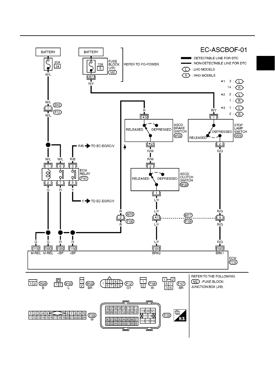
BRAKE SWITCH
EC-325
[YD (WITH EURO-OBD)]
C
D
E
F
G
H
I
J
K
L
M
A
EC
Wiring Diagram
EBS013T9
MBWA0610E
|
|
|
содержание .. 283 284 285 286 ..
BRAKE SWITCH EC-325 [YD (WITH EURO-OBD)] C D E F G H I J K L M A EC Wiring Diagram EBS013T9 MBWA0610E |