Nissan Primera P12. Manual - part 283


  Главная      Nissan     Nissan Primera P12 - Service Manual


поиск по сайту            


содержание   ..  281  282  283  284   ..


Nissan Primera P12. Manual - part 283


GLOW CONTROL SYSTEM

EC-317

[YD (WITH EURO-OBD)]

C

D

E

F

G

H

I

J

K

L

M

A

EC

GLOW CONTROL SYSTEM

PFP:25230

Description

EBS013T1

SYSTEM DESCRIPTION

When engine coolant temperature is more than approximately 80

°

C (176

°

F), the glow relay turns off.

When coolant temperature is lower than approximately 80

°

C (176

°

F):

Ignition switch ON
After ignition switch has turned to ON, the glow relay turns ON for a certain period of time in relation to
engine coolant temperature, allowing current to flow through glow plug.

Cranking
The glow relay turns ON, allowing current to flow through glow plug.

Starting
After engine has started, current continues to flow through glow plug (after-glow mode) for a certain period
in relation to engine coolant temperature.

The glow indicator lamp turns ON for a certain period of time in relation to engine coolant temperature at the
time glow relay is turned ON.

COMPONENT DESCRIPTION
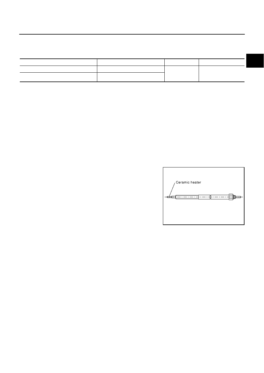
Glow Plug

The glow plug is provided with a ceramic heating element to obtain a
high-temperature resistance. It glows in response to a signal sent
from the ECM, allowing current to flow through the glow plug via the
glow relay.

Sensor

Input Signal to ECM

ECM Function

Actuator

Crankshaft position sensor

Engine speed

Glow control

Glow lamp
Glow relay
Glow plugs

Engine coolant temperature sensor

Engine coolant temperature

SEF376Y

EC-318

[YD (WITH EURO-OBD)]

GLOW CONTROL SYSTEM

Wiring Diagram

EBS013T2

MBWA0386E

GLOW CONTROL SYSTEM

EC-319

[YD (WITH EURO-OBD)]

C

D

E

F

G

H

I

J

K

L

M

A

EC

Diagnostic Procedure

EBS013T3

1.

INSPECTION START

Check fuel level, fuel supplying system, starter motor, etc.
OK or NG

OK

>> GO TO 2.

NG

>> Correct.

2.

CHECK INSTALLATION

Check that glow plug nut and all glow plug connecting plate nuts are
installed properly.
OK or NG

OK

>> GO TO 3.

NG

>> Install properly.

3.

CHECK GLOW INDICATOR LAMP OPERATION

With CONSULT-II

1.

Turn ignition switch ON.

2.

Select “COOLAN TEMP/S” in “DATA MONITOR” mode with
CONSULT-II.

3.

Confirm that “COOLAN TEMP/S” indicates below 80

°

C (176

°

F).

If it indicates above 80

°

C (176

°

F), cool down engine.

4.

Turn ignition switch OFF, wait at least 5 seconds and then turn
ON.

5.

Make sure that glow indicator lamp is turned ON for 1.5 seconds
or more after turning ignition switch ON, and then glow indicator
lamp turned OFF.

Without CONSULT-II

1.

Turn ignition switch ON.

2.

Confirm that the voltage between ECM terminal 51 (engine cool-
ant temperature sensor signal) and ground is above 1.53V.
If it is below 1.53V, cool down engine.

3.

Turn ignition switch OFF, wait at least 5 seconds and then turn
ON.

4.

Make sure that glow indicator lamp is turned ON for 1.5 seconds
or more after turning ignition switch ON, and then glow indicator
lamp turned OFF.

OK or NG

OK

>> GO TO 4.

NG

>> GO TO 5.

SEF392YA

SEF013Y

SEF006P

EC-320

[YD (WITH EURO-OBD)]

GLOW CONTROL SYSTEM

4.

CHECK GLOW CONTROL SYSTEM OVERALL FUNCTION

With CONSULT-ll

1.

Select “COOLAN TEMP/S” in “DATA MONITOR” mode with
CONSULT-II.

2.

Confirm that “COOLAN TEMP/S” indicates approximately 25

°

C

(77

°

F). If NG, cool down engine.

3.

Turn ignition switch OFF.

4.

Set voltmeter probe between glow plug and engine body.

5.

Turn ignition switch ON.

6.

Check the voltage between glow plug and engine body under
the following conditions.

Without CONSULT-II

1.

Confirm that the voltage between ECM terminal 51 (engine cool-
ant temperature sensor signal) and ground is above 3.62V.
If it is below 3.62V, cool down engine.

2.

Turn ignition switch OFF.

3.

Set voltmeter probe between glow plug and engine body.

4.

Turn ignition switch ON.

5.

Check the voltage between glow plug and engine body under
the following conditions.

OK or NG

OK

>> INSPECTION END

NG

>> GO TO 7.

5.

CHECK DTC

Check that DTC U1000 is not displayed.

Yes or No

Yes

>> Perform trouble diagnoses for DTC U1000, refer to

EC-83, "DTC U1000 CAN COMMUNICATION

LINE"

.

No

>> GO TO 6.

SEF013Y

Conditions

Voltage

For 20 seconds after turning ignition switch ON

Battery voltage

More than 20 seconds after turning ignition
switch ON

Approx. 0V

PBIB0425E

Conditions

Voltage

For 20 seconds after turning ignition switch ON

Battery voltage

More than 20 seconds after turning ignition
switch ON

Approx. 0V

SEF006P


содержание   ..  281  282  283  284   ..