Nissan Primera P12. Manual - part 271


  Главная      Nissan     Nissan Primera P12 - Service Manual


поиск по сайту            


содержание   ..  269  270  271  272   ..


Nissan Primera P12. Manual - part 271


DTC P1260 - P1267 FUEL INJECTOR ADJUSTMENT RESISTOR

EC-269

[YD (WITH EURO-OBD)]

C

D

E

F

G

H

I

J

K

L

M

A

EC

Diagnostic Procedure

EBS013QW

1.

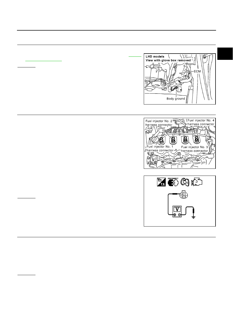
CHECK GROUND CONNECTIONS

1.

Turn ignition switch OFF.

2.

Loosen and retighten engine ground screws. Refer to

EC-82,

"Ground Inspection"

.

OK or NG

OK

>> GO TO 2.

NG

>> Repair or replace ground connections.

2.

CHECK FUEL INJECTOR ADJUSTMENT RESISTOR POWER SUPPLY CIRCUIT

1.

Disconnect fuel injector harness connector of malfunctioning
cylinder.

2.

Turn ignition switch ON.

3.

Check voltage between fuel injector terminal 2 and ground with
CONSULT-II or tester.

OK or NG

OK

>> GO TO 3.

NG

>> Repair open circuit or short to ground or short to power

in harness or connectors.

3.

CHECK FUEL INJECTOR ADJUSTMENT RESISTOR GROUND CIRCUIT

1.

Turn ignition switch OFF.

2.

Disconnect ECM harness connector.

3.

Check harness continuity between fuel injector terminal 1 and ECM terminal 78.

4.

Also check harness for short to ground and short to power.

OK or NG

OK

>> GO TO 4.

NG

>> Repair open circuit or short to ground or short to power in harness or connectors.

MBIB0915E

MBIB0085E

Voltage: Approximately 5.3V

MBIB0186E

Continuity should exist.

EC-270

[YD (WITH EURO-OBD)]

DTC P1260 - P1267 FUEL INJECTOR ADJUSTMENT RESISTOR

4.

CHECK FUEL INJECTOR ADJUSTMENT RESISTOR

Refer to

EC-270, "Component Inspection"

.

OK or NG

OK

>> GO TO 5.

NG

>> Replace fuel injector.

5.

CHECK INTERMITTENT INCIDENT

Refer to

EC-75, "TROUBLE DIAGNOSIS FOR INTERMITTENT INCIDENT"

.

>> INSPECTION END

Component Inspection

EBS013QX

FUEL INJECTOR ADJUSTMENT RESISTOR

1.

Disconnect fuel injector harness connector.

2.

Check continuity between terminals as shown in the figure.

If NG, replace fuel injector.

Removal and Installation

EBS013QY

FUEL INJECTOR

Refer to

EM-39, "INJECTION TUBE AND FUEL INJECTOR"

.

Continuity should exist.

PBIB0415E

DTC P1268 - P1271 FUEL INJECTOR

EC-271

[YD (WITH EURO-OBD)]

C

D

E

F

G

H

I

J

K

L

M

A

EC

DTC P1268 - P1271 FUEL INJECTOR

PFP:16600

Component Description

EBS013QZ

The fuel injector is a small, precise solenoid valve. When the ECM
supplies a ground to the fuel injector circuit, the coil in the fuel injec-
tor is energized. The energized coil pulls the needle valve back and
allows fuel to flow through the fuel injector into the intake cylinder.
The amount of fuel injected depends upon the injection pulse dura-
tion. Pulse duration is the length of time the fuel injector remains
open. The ECM controls the injection pulse duration based on
engine fuel needs.

CONSULT-II Reference Value in Data Monitor Mode

EBS013R0

Specification data are reference values.

ECM Terminals and Reference Value

EBS013R1

Specification data are reference values and are measured between each terminal and ground.
Pulse signal is measured by CONSULT-II.

CAUTION:

Do not use ECM ground terminals when measuring input/output voltage. Doing so may result in dam-
age to the ECM's transistor. Use a ground other than ECM terminals, such as the ground.

PBIB0465E

MONITOR ITEM

CONDITION

SPECIFICATION

MAIN INJ WID

Engine: After warming up

Shift lever: Neutral position

Idle speed

No-load

0.68 - 0.78 msec

Blower fan switch: ON
Rear window defogger switch: ON

0.78 - 0.88 msec

TERMI-

NAL

NO.

WIRE

COLOR

ITEM

CONDITION

DATA

(DC Voltage and Pulse Signal)

4

5

O/B

B

Fuel injector power supply
(For cylinder No. 1 and 4)
Fuel injector power supply
(For cylinder No. 2 and 3)

[Engine is running]

Warm-up condition

Idle speed

5 - 10V

[Engine is running]

Warm-up condition

Engine speed is 2,000 rpm

5 - 10V

MBIB0883E

MBIB0884E

EC-272

[YD (WITH EURO-OBD)]

DTC P1268 - P1271 FUEL INJECTOR

: Average voltage for pulse signal (Actual pulse signal can be confirmed by oscilloscope.)

On Board Diagnosis Logic

EBS013R2

This self-diagnosis has the one trip detection logic.
The MI will not light up for these self-diagnoses.

21
22
23
24

L
L
W
W

Fuel injector No. 2
Fuel injector No. 2
Fuel injector No. 3
Fuel injector No. 3

[Engine is running]

Warm-up condition

Idle speed

0 - 9V

[Engine is running]

Warm-up condition

Engine speed is 2,000 rpm

0 - 9V

40
41
42
43

B/P
B/P
PU/G
PU/G

Fuel injector No. 4
Fuel injector No. 4
Fuel injector No. 1
Fuel injector No. 1

[Engine is running]

Warm-up condition

Idle speed

0 - 9V

[Engine is running]

Warm-up condition

Engine speed is 2,000 rpm

0 - 9V

TERMI-

NAL

NO.

WIRE

COLOR

ITEM

CONDITION

DATA

(DC Voltage and Pulse Signal)

MBIB0881E

MBIB0882E

MBIB0881E

MBIB0882E

DTC No.

Trouble diagnosis name

DTC detecting condition

Possible cause

P1268

No. 1 cylinder fuel injector

The valve built into No. 1 cylinder fuel injector is
not closed properly (stuck open) when the injec-
tor is not energized.

Fuel injector

P1269

No. 2 cylinder fuel injector

The valve built into No. 2 cylinder fuel injector is
not closed properly (stuck open) when the injec-
tor is not energized.

P1270

No. 3 cylinder fuel injector

The valve built into No. 3 cylinder fuel injector is
not closed properly (stuck open) when the injec-
tor is not energized.

P1271

No. 4 cylinder fuel injector

The valve built into No. 4 cylinder fuel injector is
not closed properly (stuck open) when the injec-
tor is not energized.


содержание   ..  269  270  271  272   ..