содержание .. 268 269 270 271 ..
Nissan Primera P12. Manual - part 270
DTC P1212 TCS COMMUNICATION LINE
EC-265
[YD (WITH EURO-OBD)]
C
D
E
F
G
H
I
J
K
L
M
A
EC
DTC P1212 TCS COMMUNICATION LINE
PFP:47850
Description
EBS013QN
NOTE:
If DTC P1212 is displayed with DTC U1000, first perform the trouble diagnosis for DTC U1000. Refer to
EC-83, "DTC U1000 CAN COMMUNICATION LINE"
.
This CAN communication line is used to control the smooth engine operation during the TCS operation. Pulse
signals are exchanged between ECM and ESP/TCS/ABS control unit.
Be sure to erase the malfunction information such as DTC not only for ESP/TCS/ABS control unit but
also for ECM after TCS related repair.
On Board Diagnosis Logic
EBS013QO
This self-diagnosis has the one trip detection logic.
The MI will not light up for this self-diagnosis.
DTC Confirmation Procedure
EBS013QP
NOTE:
If DTC Confirmation Procedure has been previously conducted, always turn ignition switch OFF and wait at
least 10 seconds before conducting the next test.
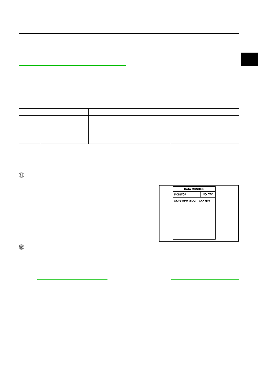
WITH CONSULT-II
1.
Turn ignition switch ON.
2.
Select “DATA MONITOR” mode with CONSULT-II.
3.
Wait at least 5 seconds.
4.
If DTC is detected, go to
EC-265, "Diagnostic Procedure"
.
WITH GST
Follow the procedure “WITH CONSULT-II” above.
Diagnostic Procedure
EBS013QQ
1.
CHECK ESP/TCS/ABS CONTROL UNIT FUNCTION
Refer to
(models with ESP system) or
(models without ESP system).
>> INSPECTION END
DTC No.
Trouble diagnosis name
DTC detecting condition
Possible cause
P1212
TCS communication line
ECM can not receive the information from ESP/
TCS/ABS control unit continuously.
●
Harness or connectors
(The CAN communication line is
open or shorted.)
●
ESP/TCS/ABS control unit
●
Dead (Weak) battery
SEF817Y