Nissan Primera P12. Manual - part 110


  Главная      Nissan     Nissan Primera P12 - Service Manual


поиск по сайту            


содержание   ..  108  109  110  111   ..


Nissan Primera P12. Manual - part 110


THEFT WARNING SYSTEM

BL-149

C

D

E

F

G

H

J

K

L

M

A

B

BL

Hazard Lamp Alarm Check

EIS005J3

1.

CHECK HAZARD WARNING LAMP

Check if hazard warning lamp flashes with hazard switch.
Does hazard warning lamp operate?

Yes

>> GO TO 2.

No

>> Check hazard warning lamp circuit.

2.

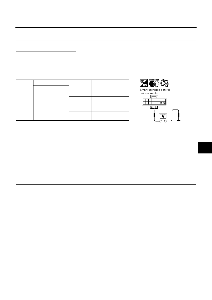
CHECK HAZARD REMINDER OPERATION

Check voltage between smart entrance control unit harness connector and ground.

OK or NG

OK

>> Check harness for open or short between smart entrance control unit and hazard switch.

NG

>> Replace smart entrance control unit.

Security Indicator Lamp Check

EIS005J4

1.

CHECK FUSE

Check 10A fuse [No.12, located in the fuse block (J/B)]

Check 10A fuse [No.30, located in the fuse block (J/B)]

OK or NG

OK

>> GO TO 2

NG

>> If fuse is blown, be sure to eliminate cause of malfunction before installing new fuse.

2.

CHECK SECURITY INDICATOR LAMP

1.

Perform initialization with CONSULT-II.
For initialization, refer to “CONSULT-II Operation Manual NATS”.

2.

Turn ignition switch OFF.

3.

Start engine and turn ignition switch OFF.

4.

Check the security indicator lamp lighting.

Security indicator lamp should be light up?

Yes

>> Inspection END.

No

>> GO TO 3

Connector

Terminals (wire color)

Remote con-

troller

Voltage (V)

(Approx.)

(+)

(

)

M43

5 (B/R)

Ground

Lock

0

Battery voltage

0

Unlock

0

Battery voltage

0

Battery voltage

0

64 (G/B)

Lock

0

Battery voltage

0

Unlock

0

Battery voltage

0

Battery voltage

0

MIIB0473E

BL-150

THEFT WARNING SYSTEM

3.

CHECK SECURITY INDICATOR LAMP POWER SUPPLY CIRCUIT

1.

Disconnect combination meter connector.

2.

Check voltage between combination meter harness connector
M37 terminal 38, 39 (RHD models) or 51, 52 (LHD models) and
ground.

OK or NG

OK

>> GO TO 4

NG

>> Check harness for open or short between fuse and

security indicator lamp.

4.

CHECK SMART ENTRANCE CONTROL UNIT FUNCTION

Check continuity between smart entrance control unit harness con-
nector M42 terminal 34 and ground.

OK or NG

OK

>> Check harness for open or short between smart

entrance control unit and combination meter.

NG

>> Smart entrance control unit is malfunctioning.

Replace smart entrance control unit

Perform initialization with CONSULT-II

For initialization, refer to “CONSULT-II operation manual NATS”

38 - Ground

: Battery voltage

39 - Ground

: Battery voltage

51 - Ground

: Battery voltage

52 - Ground

: Battery voltage

SIIA1653E

34 (L/Y) - Ground

: Continuity should exist
intermittently.

SIIA1654E

NATS (NISSAN ANTI-THEFT SYSTEM)

BL-151

C

D

E

F

G

H

J

K

L

M

A

B

BL

NATS (NISSAN ANTI-THEFT SYSTEM)

PFP:25386

Component Parts and Harness Connector Location

EIS005J6

SIIA1647E

BL-152

NATS (NISSAN ANTI-THEFT SYSTEM)

System Description

EIS005J7

NATS (Nissan Anti-Theft System) has the following immobilizer functions:

Since only NATS ignition keys, whose ID nos. have been registered into the ECM and IMMU (Smart
entrance control unit) of NATS, allow the engine to run, operation of a stolen vehicle without a NATS reg-
istered key is prevented by NATS.
That is to say, NATS will immobilize the engine if someone tries to start it without the registered key of
NATS.

This version of NATS has dongle unit to improve its anti-theft performance (RHD models). Dongle unit has
its own ID which is registered into NATS IMMU (Smart entrance control unit). So if dongle unit is replaced,
initialization must be carried out.

When dongle unit has a malfunction of dongle unit is detected:
The security indicator lamp illuminates for about 15 minutes after ignition switch is turned to ON.
When dongle unit has a malfunction and the indicator lamp is illuminated, engine can not be started. How-
ever engine can be started only one time when security indicator lamp turns off in about 15 minutes after
ignition switch is turned to ON.

All of the originally supplied ignition key IDs have been NATS registered.
If requested by the vehicle owner, a maximum of five key IDs can be registered into the NATS compo-
nents.

The security indicator blinks when the ignition switch is in “OFF” or “ACC” position. Therefore, NATS
warns outsiders that the vehicle is equipped with the anti-theft system.

When NATS detects trouble, the security indicator lamp lights up as follows.

NATS trouble diagnoses, system initialization and additional registration of other NATS ignition key IDs
must be carried out using CONSULT-II hardware and CONSULT-II NATS software.
Regarding the procedures of NATS initialization and NATS ignition key ID registration, refer to CONSULT-
II operation manual, NATS.

When servicing a malfunction of the NATS (indicated by lighting up of Security Indicator Lamp) or
registering another NATS ignition key ID no., it may be necessary to re-register original key iden-
tification. Therefore, be sure to receive ALL KEYS from vehicle owner.

Condition IGN ON and

Security indicator

With dongle

With out dongle

NATS malfunction (except dongle unit) is detected

1. 6 time blinking

2. Staying ON after ignition switch is

turned ON

Staying ON

Only malfunction of dongle unit is detected.

Stay ON for about 15 minutes after
ignition switch is turned ON

Malfunction of NATS and engine related parts are
detected

1. 6 time blinking

2. Staying ON after ignition switch is

turned ON

Staying ON

Only engine related part malfunction is detected.

Just after initialization of NATS

6 time blinking


содержание   ..  108  109  110  111   ..