Nissan Primera P12. Manual - part 89


  Главная      Nissan     Nissan Primera P12 - Service Manual


поиск по сайту            


содержание   ..  87  88  89  90   ..


Nissan Primera P12. Manual - part 89


POWER DOOR LOCK — SUPER LOCK —

BL-65

C

D

E

F

G

H

J

K

L

M

A

B

BL

REAR RH SIDE

1.

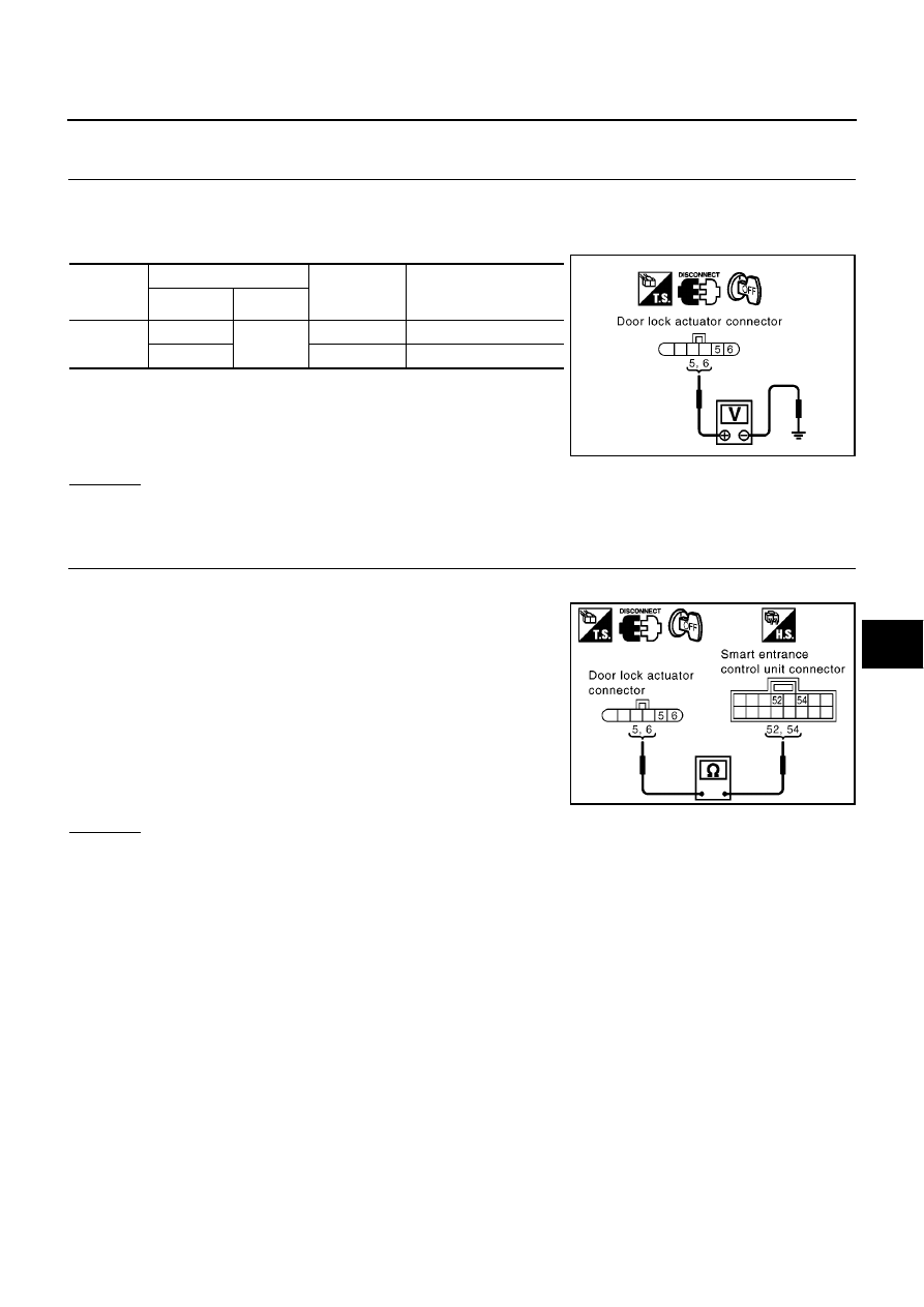
CHECK DOOR LOCK SIGNAL

1.

Turn ignition switch OFF.

2.

Disconnect rear door lock actuator RH harness connector.

3.

Check voltage between rear door lock actuator RH harness connector and ground.

OK or NG

OK

>> Replace rear door lock actuator RH.

NG

>> GO TO 2.

2.

CHECK DOOR LOCK ACTUATOR CIRCUIT

1.

Disconnect smart entrance control unit harness connector.

2.

Check continuity between rear door lock actuator RH harness
connector D66 terminal 5, 6 and smart entrance control unit har-
ness connector M43 terminal 52, 54.

OK or NG

OK

>> Replace smart entrance control unit.

NG

>> Repair or replace harness between smart entrance control unit and rear door lock actuator RH.

Connector

Terminals (wire color)

Door lock/

unlock switch

condition

Voltage (V)

(Approx.)

(+)

(

)

D66

5 (Y)

Ground

Lock

0

Battery voltage

0

6 (G/Y)

Unlock

0

Battery voltage

0

MIIB0463E

5 (Y) - 52 (Y)

: Continuity should exist.

6 (G/Y) - 54 (G/Y)

: Continuity should exist.

MIIB0467E

BL-66

POWER DOOR LOCK — SUPER LOCK —

Door Switch Check

EIS005HH

DRIVER SIDE

1.

CHECK DOOR SWITCH INPUT SIGNAL

WITH CONSULT-II

Check driver door switch signal (“DR DOOR SW”) in “DATA MONITOR” mode with CONSULT-II.

WITHOUT CONSULT-II

1.

Turn ignition switch OFF.

2.

Check voltage between smart entrance control unit harness
connector and ground.

OK or NG

OK

>> Door switch (driver side) is OK.

NG

>> GO TO 2.

2.

CHECK DRIVER SIDE DOOR SWITCH

1.

Disconnect front door switch (driver side) connector.

2.

Check continuity between front door switch (driver side) terminal
1 and ground part of door switch.

OK or NG

OK

>> Check harness for open or short between smart

entrance control unit and front door switch (driver side).

NG

>> Replace front door switch (driver side).

DR DOOR SW

Driver side door is open

: ON

Driver side door is closed

: OFF

MKIB0197E

Connector

Terminal (wire color)

Driver side door

condition

Voltage (V)

(Approx.)

( + )

( - )

M42

43 (R/W)

Ground

Open : (ON)

0

Closed : (OFF)

Battery voltage

MKIB0073E

Terminal

Door switch

Continuity

1

Ground part of
door switch

Pushed

No

Released

Yes

PIIA3351E

POWER DOOR LOCK — SUPER LOCK —

BL-67

C

D

E

F

G

H

J

K

L

M

A

B

BL

EXCEPT DRIVER SIDE

1.

CHECK OTHER DOORS SWITCHES INPUT SIGNAL

WITH CONSULT-II

Check other doors switch signal (“AS DOOR SW”, “RR DOOR SW” or “RR RH DOOR SW”) in “DATA MONI-
TOR” mode with CONSULT-II.

WITHOUT CONSULT-II

Check voltage between smart entrance control unit harness connector and ground.

OK or NG

OK

>> Door switch OK.

NG

>> GO TO 2.

2.

CHECK DOOR SWITCHES

1.

Disconnect each door switches harness connector.

2.

Check continuity between door switch terminal 1 and ground
part of door switch.

OK or NG

OK

>> Check harness for open or short between smart

entrance control unit and door switch.

NG

>> Replace malfunction door switch.

Each DOOR SW

Each door is open

: ON

Each door is closed

: OFF

MKIB0199E

Item

Connector

Terminal (wire color)

Condition

Voltage (V)

(Approx.)

(+)

(

)

Rear door
LH or RH

M42

39 (BR/W)

Ground

Open

0

Closed

Battery voltage

Passenger
side

44 (L/OR)

Open

0

Closed

Battery voltage

Rear door
LH or RH

45 (R/Y)

Open

0

Closed

Battery voltage

MKIB0583E

Terminal

Condition

Continuity

1

Ground part of

door switch

Pushed

No

Released

Yes

MKIB0584E

BL-68

POWER DOOR LOCK — SUPER LOCK —

Trunk Room Lamp Switch or Back Door Switch Check

EIS005HI

TRUNK ROOM LAMP SWITCH

1.

CHECK TRUNK ROOM LAMP SWITCH INPUT SIGNAL

With CONSULT- II

Check door switch “TRUNK OPEN SWITCH” in “DATA MONITOR” mode with CONSULT- II.

Without CONSULT- II

Check voltage between smart entrance control unit harness connector and ground.

OK or NG

OK

>> Trunk room lamp switch is OK.

NG

>> GO TO 2

2.

CHECK TRUNK ROOM LAMP SWITCH

1.

Turn ignition switch OFF.

2.

Disconnect trunk room lamp switch harness connector.

3.

Check continuity between trunk room lamp switch terminals 1 and 2.

OK or NG

OK

>> Check the following.

Trunk room lamp switch ground circuit

Harness for open or short between smart entrance
control unit and trunk room lamp switch

NG

>> Replace trunk room lamp switch.

TRUNK OPEN SW

Trunk lid open

: ON

Trunk lid close

: OFF

SIIA1635E

Connector

Terminal (wire color)

Trunk lid

Voltage (V)

(Approx.)

(+)

(–)

M41

16 (G)

Ground

Closed

5

Open

0

SIIA1636E

Terminal

Trunk lid condition

Continuity

1

2

Opened

Yes

Closed

No

SIIA1637E


содержание   ..  87  88  89  90   ..