содержание .. 85 86 87 88 ..
Nissan Primera P12. Manual - part 87
POWER DOOR LOCK — SUPER LOCK —
BL-57
C
D
E
F
G
H
J
K
L
M
A
B
BL
Trouble Diagnoses
EIS005HC
First perform the “SELF-DIAG RESULTS” in “SMART ENTRANCE” with CONSULT-II, when perform the each
trouble diagnosis. Refer to
BCS-13, "CONSULT-II INSPECTION PROCEDURE"
.
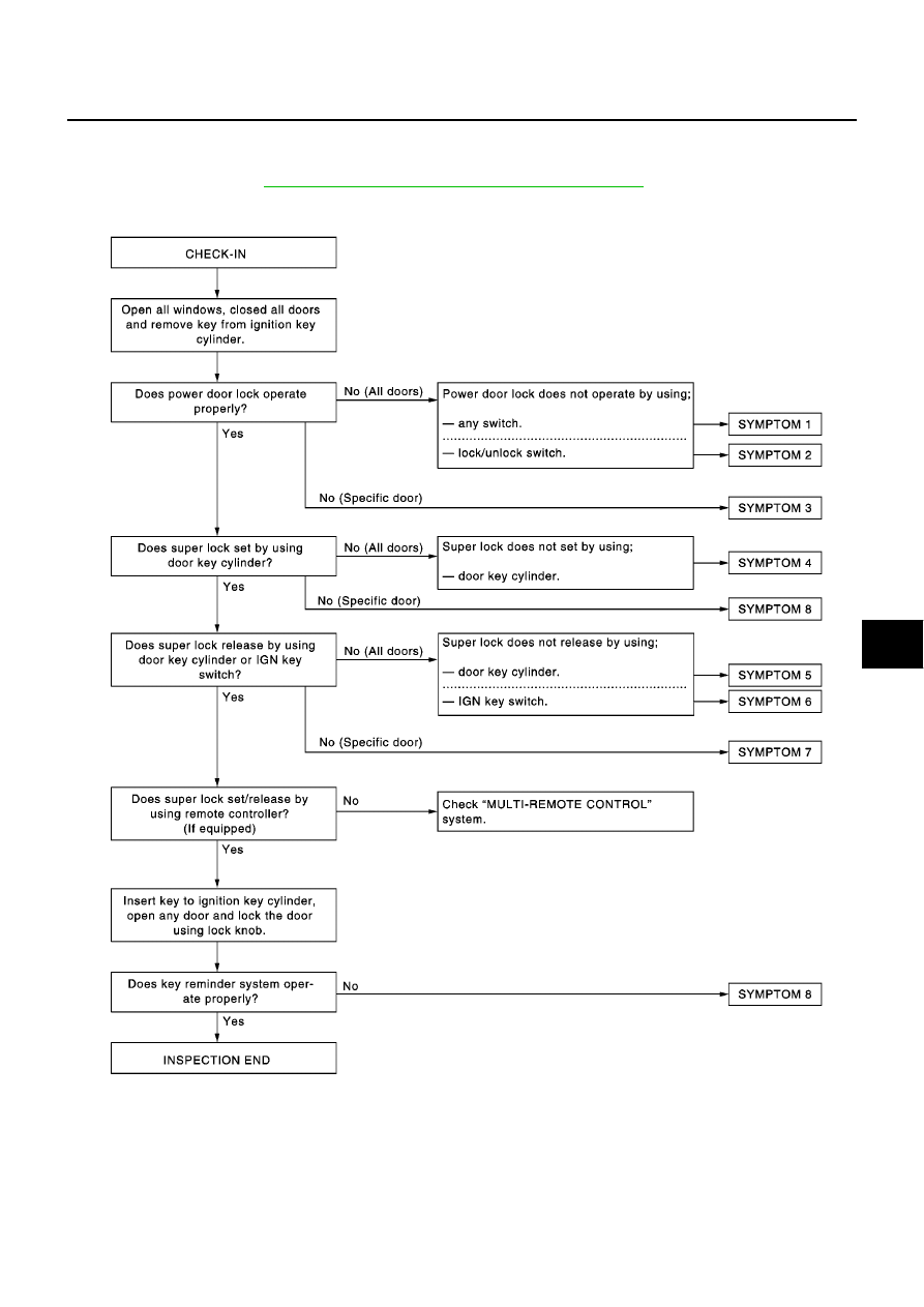
PRELIMINARY CHECK
After performing preliminary check, go to SYMPTOM CHART.
Before starting trouble diagnoses below, perform preliminary check.
Symptom numbers in the symptom chart correspond with those of Preliminary check.
SIIA1601E