Nissan Primera P12. Manual - part 90


  Главная      Nissan     Nissan Primera P12 - Service Manual


поиск по сайту            


содержание   ..  88  89  90  91   ..


Nissan Primera P12. Manual - part 90


POWER DOOR LOCK — SUPER LOCK —

BL-69

C

D

E

F

G

H

J

K

L

M

A

B

BL

BACK DOOR SWITCH

1.

CHECK BACK DOOR SWITCH INPUT SIGNAL

With CONSULT- II

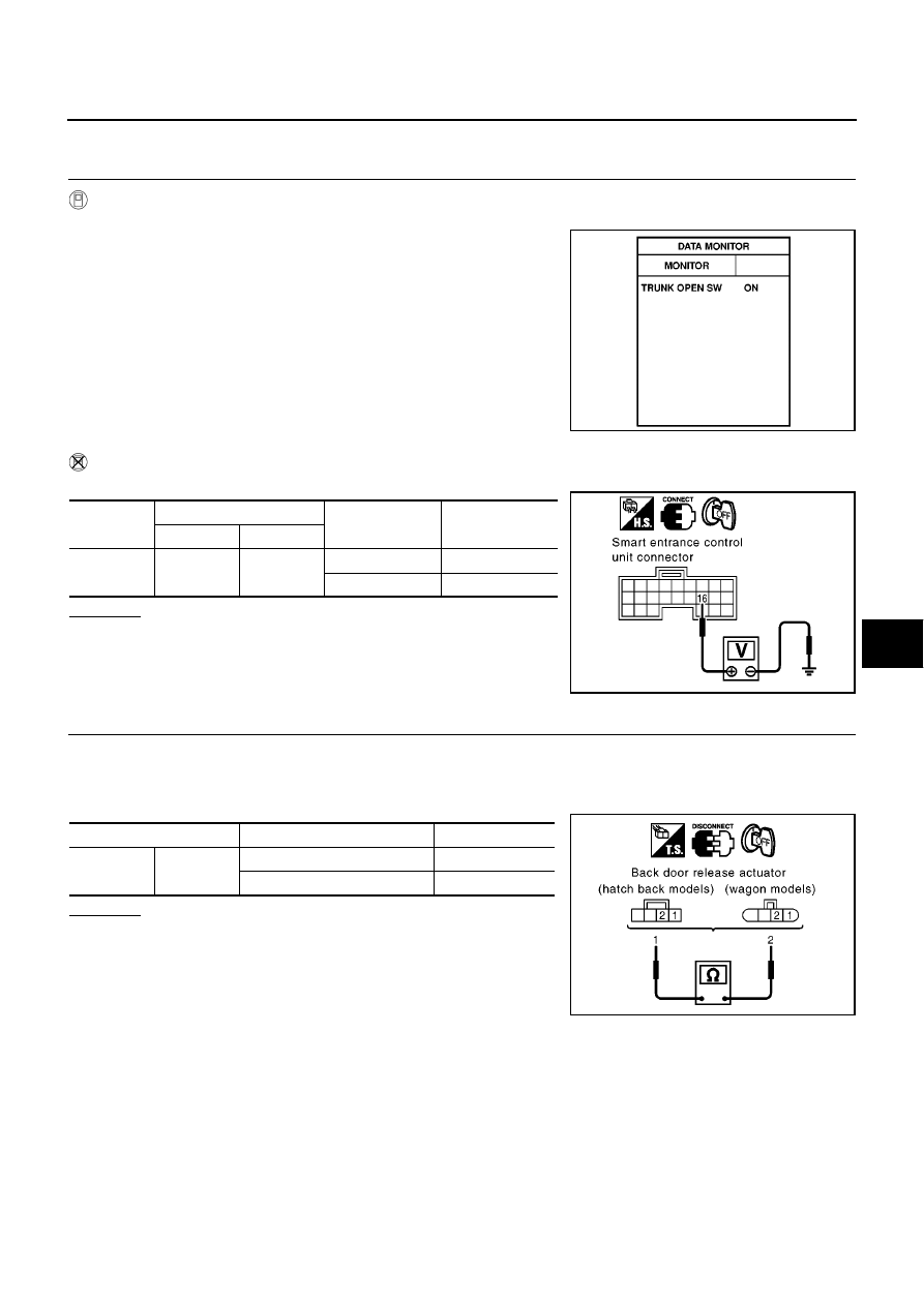
Check door switch “TRUNK OPEN SWITCH” in “DATA MONITOR” mode with CONSULT- II.

Without CONSULT- II

Check voltage between smart entrance control unit harness connector and ground.

OK or NG

OK

>> Back door switch is OK.

NG

>> GO TO 2

2.

CHECK BACK DOOR SWITCH

1.

Turn ignition switch OFF.

2.

Disconnect back door release actuator connector.

3.

Check continuity between back door release actuator terminals 1 and 2.

OK or NG

OK

>> Check the following.

Back door release actuator ground circuit

Harness for open or short between smart entrance
control unit and back door release actuator

NG

>> Replace back door release actuator.

TRUNK OPEN SW

Back door open

: ON

Back door close

: OFF

SIIA1635E

Connector

Terminal (wire color)

Back door

Voltage (V)

(Approx.)

(+)

(–)

M41

16 (G)

Ground

Closed

5

Open

0

SIIA1636E

Terminal

Back door condition

Continuity

1

2

Opened

Yes

Closed

No

MIIB0456E

BL-70

POWER DOOR LOCK — SUPER LOCK —

Key Switch Check

EIS005HJ

1.

CHECK KEY SWITCH INPUT SIGNAL

WITH CONSULT-II

Check key switch signal (“KEY IN DETECT”) in “DATA MONITOR”
mode with CONSULT-II.

WITHOUT CONSULT-II

Check voltage between smart entrance control unit harness connector M41 terminal 5 and ground.

OK or NG

OK

>> Key switch is OK.

NG

>> GO TO 2.

2.

CHECK KEY SWITCH

1.

Disconnect key switch connector.

2.

Check continuity between key switch terminal 1 and 2.

OK or NG

OK

>> Check the following.

10A fuse [No. 12, located in fuse block (J/B)]

Harness for open or short between key switch and
fuse

Harness for open or short between smart entrance control unit and key switch

NG

>> Replace key switch.

KEY IN DETECT

Key is inserted in ignition cylinder

: ON

Key is removed from ignition key cylinder

: OFF

MKIB0200E

Connector

Terminals (wire color)

Condition

(Door lock/

unlock switch)

Voltage (V)

(Approx.)

(+)

(

)

M41

5 (B/R)

Ground

Key is

inserted

Battery voltage

Key is

removed

0

MKIB0585E

Terminal

Condition

Continuity

1

2

Key is inserted

Yes

Key is removed

No

MKIB0586E

POWER DOOR LOCK — SUPER LOCK —

BL-71

C

D

E

F

G

H

J

K

L

M

A

B

BL

Super Lock Actuator Check

EIS005HK

FRONT DOOR

1.

CHECK OUTPUT SIGNAL FOR SUPER LOCK ACTUATOR

Check voltage between smart entrance control unit harness connector and ground.

OK or NG

OK

>> GO TO 2.

NG

>> Replace smart entrance control unit.

2.

CHECK SUPER LOCK ACTUATOR CIRUIT

1.

Turn ignition switch OFF.

2.

Disconnect smart entrance control unit and front door lock actuator assembly connector.

3.

Check continuity between smart entrance control unit harness
connector M43 terminal 52, 55 and front door lock actuator har-
ness connector D9 (driver side) or D38 (passenger side) termi-
nal 1, 2 (driver side) or 5, 6 (passenger side).

OK or NG

OK

>> Replace front door lock actuator (driver side) or (passenger side).

NG

>> Repair or replace harness between smart entrance control unit and front door lock actuator (driver

side) or (passenger side).

REAR DOOR

1.

CHECK OUTPUT SIGNAL FOR SUPER LOCK ACTUATOR

Check voltage between smart entrance control unit harness connector and ground.

OK or NG

OK

>> GO TO 2

NG

>> Replace smart entrance control unit.

Connector

Terminals (wire color)

Door lock/

unlock switch

condition

Voltage (V)

(Approx.)

(+)

(

)

M43

52 (Y)

Ground

Unlock

(Released)

0

Battery voltage

0

55 (W/B)

Lock (Set)

0

Battery voltage

0

MIIB0468E

Driver side

52 (Y) - 2 (Y)

: Continuity should exist.

55 (W/B) - 1 (W/B)

: Continuity should exist.

Passenger side

52 (Y) - 5 (Y)

: Continuity should exist.

55 (W/B) - 6 (W/B)

: Continuity should exist.

MIIB0469E

Connector

Terminals (wire color)

Door lock/

unlock switch

condition

Voltage (V)

(Approx.)

(+)

(

)

M43

50 (G)

Ground

Lock (Set)

0

Battery voltage

0

52 (Y)

Unlock

(Released)

0

Battery voltage

0

MIIB0470E

BL-72

POWER DOOR LOCK — SUPER LOCK —

2.

CHECK SUPER LOCK ACTUATOR

1.

Turn ignition switch OFF.

2.

Disconnect smart entrance control unit and rear door lock actuator assembly connector.

3.

Check continuity between smart entrance control unit harness
connector M43 terminal 50, 52 and rear door lock actuator har-
ness connector D56 (LH) terminal 2, 5 or D66 (RH) terminal 2, 5.

OK or NG

OK

>> Replace rear door lock actuator LH or RH.

NG

>> Repair or replace harness between smart entrance control unit and rear door lock actuator LH or

RH.

Trunk or Back Door Release Switch Check

EIS005HL

EXTERNAL SWITCH

1.

CHECK EXTERNAL TRUNK OR BACK DOOR RELEASE SWITCH INPUT SIGNAL

With CONSULT-II

Check external trunk or back door release switch input signal “EXT TRUNK REL” in “DATA MONITOR” mode
with CONSULT- II.

Without CONSULT- II

Check voltage between smart entrance control unit harness connector M41 terminal 20(BR) and ground.

OK or NG

OK

>> Trunk or back door release switch is OK.

NG

>> GO TO 2

Rear LH

50 (G) - 5 (G)

: Continuity should exist.

52 (Y) - 2 (Y)

: Continuity should exist.

Rear RH

50 (G) - 2 (G)

: Continuity should exist.

52 (Y) - 5 (Y)

: Continuity should exist.

MIIB0471E

Release switch is pushed (open):

EXT TRUNK REL ON

Release switch is released (close):

EXT TRUNK REL OFF

SIIA1603E

Connector

Terminal (wire color)

Release switch

Voltage (V)

(Approx.)

(+)

(–)

M41

20 (B/R)

Ground

Pushed

0

Released

5

SIIA1604E


содержание   ..  88  89  90  91   ..