содержание .. 34 35 36 37 ..
Nissan Primera P12. Manual - part 36
REFRIGERANT LINES
ATC-137
C
D
E
F
G
H
I
K
L
M
A
B
ATC
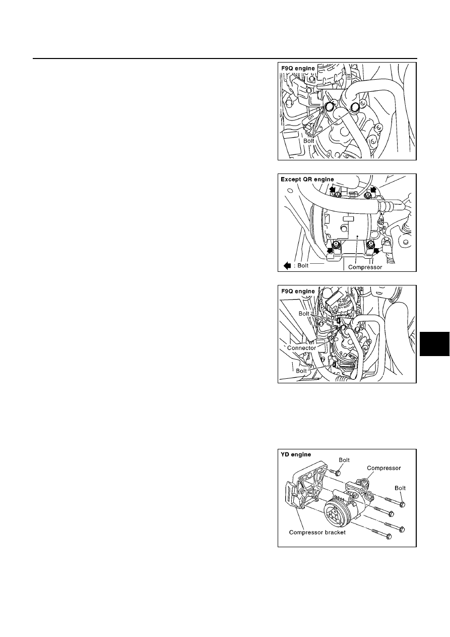
6.
Remove the mounting bolts from compressor.
7.
Remove the compressor from the lower side of the vehicle.
INSTALLATION
CAUTION:
●
Replace the O-ring of the low-pressure flexible hose and high-pressure flexible hose with a new
one, then apply compressor oil to it when installing it.
●
When pouring refrigerant, check for leaks.
RJIA2373E
RJIA0818E
RJIA2374E
Compressor mounting bolt (YD engine)
Tightening torque:
60 - 69 N·m (6.1 - 7.1 kg-m, 45 - 51
ft-lb)
Compressor bracket mounting bolt (YD engine)
Tightening torque:
57 - 65 N·m (5.8 - 6.7 kg-m, 42 - 48
ft-lb)
RJIA0838E