Qashqai J11. Door & Lock - part 36
POWER SUPPLY AND GROUND CIRCUIT
DLK-577
< DTC/CIRCUIT DIAGNOSIS >
[TYPE 4]
C
D
E
F
G
H
I
J
L
M
A
B
DLK
N
O
P
POWER SUPPLY AND GROUND CIRCUIT
FRONT DOOR
FRONT DOOR : Diagnosis Procedure
INFOID:0000000010487321
1.
CHECK FUSE
Check that the following fuse is not fusing.
Is the fuse fusing?
YES
>> Replace the blown fuse after repairing the affected circuit if a fuse is blown.
NO
>> GO TO 2.
2.
CHECK POWER SUPPLY CIRCUIT
1.
Turn ignition switch OFF.
2.
Disconnect BCM connectors.
3.
Check voltage between BCM harness connector and ground.
Is the measurement value normal?
YES
>> GO TO 3.
NO
>> Repair or replace harness.
3.
CHECK GROUND CIRCUIT
Check continuity between BCM harness connector and ground.
Is the inspection result normal?
YES
>> INSPECTION END
NO
>> Repair or replace harness.
REAR DOOR
REAR DOOR : Diagnosis Procedure
INFOID:0000000010487322
1.
CHECK FUSE
Check that the following fuse is not fusing.
Is the fuse fusing?
YES
>> Replace the blown fuse after repairing the affected circuit if a fuse is blown.
NO
>> GO TO 2.
2.
CHECK POWER SUPPLY CIRCUIT
1.
Turn ignition switch OFF.
2.
Disconnect BCM connectors.
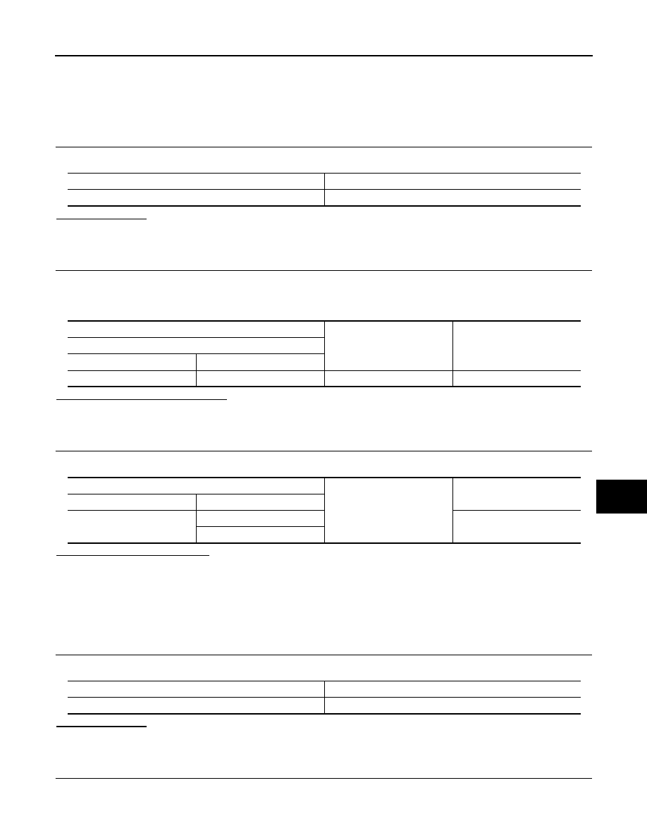
Signal name
Fuse No.
Front door lock actuator power supply
29 (15 A)
(+)
(
−
)
Voltage
BCM
Connector
Terminal
M68
143
Ground
9 – 16 V
BCM
Ground
Continuity
Connector
Terminal
M68
146
Existed
147
Signal name
Fuse No.
Passenger door and rear door lock actuator power supply
31 (15 A)