Qashqai J11. Door & Lock - part 35
 

  Index      Nissan     Qashqai J11. Door & Lock. Service and Repair Manual


Search            copyright infringement  


Content      ..     33      34      35      36     ..


Qashqai J11. Door & Lock - part 35


DOOR LOCK ACTUATOR

DLK-561

< DTC/CIRCUIT DIAGNOSIS >

[TYPE 4]

C

D

E

F

G

H

I

J

L

M

A

B

DLK

N

O

P

RHD models

3.

Check continuity between BCM harness connector and ground.

Is the inspection result normal?

YES

>> GO TO 3.

NO

>> Repair or replace harness.

3.

CHECK BCM OUTPUT SIGNAL

1.

Connect BCM connector.

2.

Check voltage between BCM harness connector and ground.

Is the inspection result normal?

YES

>> Check for internal short of each door lock actuator.

NO

>> Replace BCM. Refer to 

BCS-135, "Removal and Installation"

.

PASSENGER SIDE

PASSENGER SIDE : Component Function Check

INFOID:0000000010504762

1.

CHECK FUNCTION

1.

Select “DOOR LOCK” of “BCM” using CONSULT.

2.

Select “DOOR LOCK” in “ACTIVE TEST” mode.

3.

Check that the function operates normally according to the following conditions.

Is the inspection result normal?

YES

>> Door lock actuator is OK.

NO

>> Refer to 

DLK-560, "DRIVER SIDE : Diagnosis Procedure"

.

PASSENGER SIDE : Diagnosis Procedure

INFOID:0000000010504763

1.

CHECK DOOR LOCK ACTUATOR INPUT SIGNAL

1.

Turn ignition switch OFF.

2.

Disconnect front door lock assembly (passenger side) connector.

3.

Check voltage between front door lock assembly (passenger side) harness connector and ground.

BCM

Front door lock assembly (driver side)

Continuity 

Connector

Terminal

Connector

Terminal

M68

141

D25

3

Existed

148

2

BCM

Ground

Continuity 

Connector

Terminal

M68

141

Not existed

148

(+)

(–)

Condition

Voltage

BCM

Connector

Terminal

M68

141

Ground

Door lock and unlock switch

Lock

9 – 16 V

148

Unlock

Monitor item

Status

DOOR LOCK

ALL LOCK

Door lock actuators

LOCK

ALL UNLOCK

UNLOCK

DLK-562

< DTC/CIRCUIT DIAGNOSIS >

[TYPE 4]

DOOR LOCK ACTUATOR

LHD models

RHD models

Is the inspection result normal?

YES

>> Replace front door lock assembly (passenger side).

NO

>> GO TO 2.

2.

CHECK DOOR LOCK ACTUATOR CIRCUIT

1.

Disconnect BCM connector and all door lock assembly connector. 

2.

Check continuity between BCM harness connector and front door lock assembly (passenger side) har-
ness connector. 

LHD models

RHD models

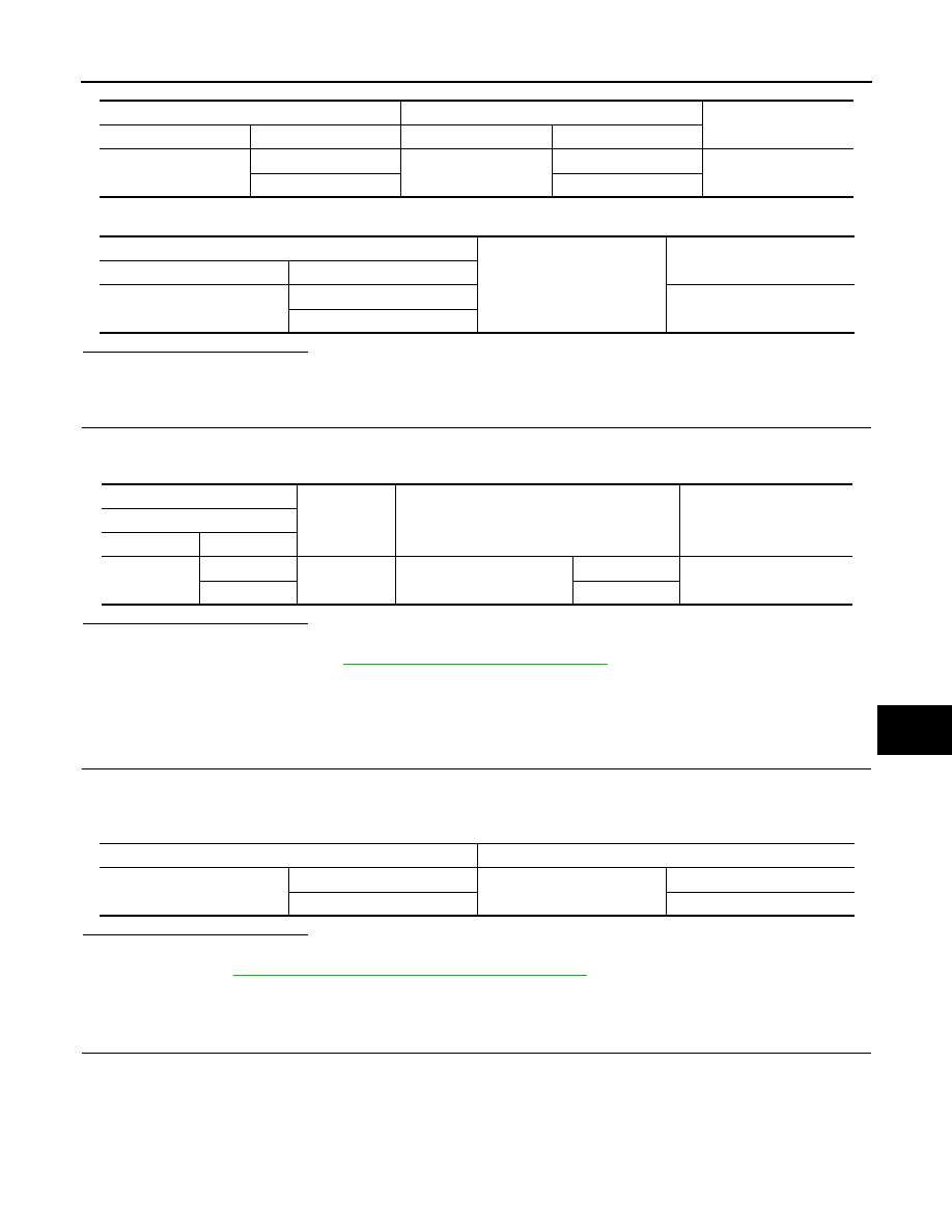
3.

Check continuity between BCM harness connector and ground.

Is the inspection result normal?

YES

>> GO TO 3.

NO

>> Repair or replace harness.

3.

CHECK BCM OUTPUT SIGNAL

1.

Connect BCM connector.

2.

Check voltage between BCM harness connector and ground.

(+)

(–)

Condition

Voltage

Front door lock assembly

(passenger side)

Connector

Terminal

D25

2

Ground

Door lock and unlock switch

Unlock

9 – 16 V

3

Lock

(+)

(–)

Condition

Voltage

Front door lock assembly

(passenger side)

Connector

Terminal

D1

2

Ground

Door lock and unlock switch

Unlock

9 – 16 V

3

Lock

BCM

Front door lock assembly (passenger side)

Continuity 

Connector

Terminal

Connector

Terminal

M68

139

D25

2

Existed

141

3

BCM

Front door lock assembly (passenger side)

Continuity 

Connector

Terminal

Connector

Terminal

M68

139

D1

2

Existed

141

3

BCM

Ground

Continuity 

Connector

Terminal

M68

139

Not existed

141

DOOR LOCK ACTUATOR

DLK-563

< DTC/CIRCUIT DIAGNOSIS >

[TYPE 4]

C

D

E

F

G

H

I

J

L

M

A

B

DLK

N

O

P

Is the inspection result normal?

YES

>> Check for internal short of each door lock actuator.

NO

>> Replace BCM. Refer to 

BCS-135, "Removal and Installation"

.

REAR LH

REAR LH : Component Function Check

INFOID:0000000010504764

1.

CHECK FUNCTION

1.

Select “DOOR LOCK” of “BCM” using CONSULT.

2.

Select “DOOR LOCK” in “ACTIVE TEST” mode.

3.

Check that the function operates normally according to the following conditions.

Is the inspection result normal?

YES

>> Door lock actuator is OK.

NO

>> Refer to 

DLK-560, "DRIVER SIDE : Diagnosis Procedure"

.

REAR LH : Diagnosis Procedure

INFOID:0000000010504765

1.

CHECK DOOR LOCK ACTUATOR INPUT SIGNAL

1.

Turn ignition switch OFF.

2.

Disconnect rear door lock assembly LH connector.

3.

Check voltage between rear door lock assembly LH harness connector and ground.

Is the inspection result normal?

YES

>> Replace rear door lock assembly LH.

NO

>> GO TO 2.

2.

CHECK DOOR LOCK ACTUATOR CIRCUIT

1.

Disconnect BCM connector and all door lock assembly connector.

2.

Check continuity between BCM harness connector and rear door lock assembly LH harness connector. 

3.

Check continuity between BCM harness connector and ground.

(+)

(–)

Condition

Voltage

BCM

Connector

Terminal

M68

139

Ground

Door lock and unlock switch

Unlock

9 – 16 V

141

Lock

Monitor item

Status

DOOR LOCK

ALL LOCK

Door lock actuators

LOCK

ALL UNLOCK

UNLOCK

(+)

(–)

Condition

Voltage

Rear door lock assembly LH

Connector

Terminal

D51

2

Ground

Door lock and unlock switch

Unlock

9 – 16 V

3

Lock

BCM

Rear door lock assembly LH

Continuity 

Connector

Terminal

Connector

Terminal

B3

124

D51

2

Existed

125

3

DLK-564

< DTC/CIRCUIT DIAGNOSIS >

[TYPE 4]

DOOR LOCK ACTUATOR

Is the inspection result normal?

YES

>> GO TO 3.

NO

>> Repair or replace harness.

3.

CHECK BCM OUTPUT SIGNAL

1.

Connect BCM connector.

2.

Check voltage between BCM harness connector and ground.

Is the inspection result normal?

YES

>> Check for internal short of each door lock actuator.

NO

>> Replace BCM. Refer to 

BCS-135, "Removal and Installation"

.

REAR RH

REAR RH : Component Function Check

INFOID:0000000010504766

1.

CHECK FUNCTION

1.

Select “DOOR LOCK” of “BCM” using CONSULT.

2.

Select “DOOR LOCK” in “ACTIVE TEST” mode.

3.

Check that the function operates normally according to the following conditions.

Is the inspection result normal?

YES

>> Door lock actuator is OK.

NO

>> Refer to 

DLK-560, "DRIVER SIDE : Diagnosis Procedure"

.

REAR RH : Diagnosis Procedure

INFOID:0000000010504767

1.

CHECK DOOR LOCK ACTUATOR INPUT SIGNAL

1.

Turn ignition switch OFF.

2.

Disconnect rear door lock assembly RH connector.

3.

Check voltage between rear door lock assembly RH harness connector and ground.

Is the inspection result normal?

YES

>> Replace rear door lock assembly RH.

NO

>> GO TO 2.

BCM

Ground

Continuity 

Connector

Terminal

B3

124

Not existed

125

(+)

(–)

Condition

Voltage

BCM

Connector

Terminal

B3

124

Ground

Door lock and unlock switch

Unlock

9 – 16 V

125

Lock

Monitor item

Status

DOOR LOCK

ALL LOCK

Door lock actuators

LOCK

ALL UNLOCK

UNLOCK

(+)

(–)

Condition

Voltage

Rear door lock assembly RH

Connector

Terminal

D64

2

Ground

Door lock and unlock switch

Unlock

9 – 16 V

3

Lock

DOOR LOCK ACTUATOR

DLK-565

< DTC/CIRCUIT DIAGNOSIS >

[TYPE 4]

C

D

E

F

G

H

I

J

L

M

A

B

DLK

N

O

P

2.

CHECK DOOR LOCK ACTUATOR CIRCUIT

1.

Disconnect BCM connector and all door lock assembly connector.

2.

Check continuity between BCM harness connector and rear door lock assembly RH harness connector. 

3.

Check continuity between BCM harness connector and ground.

Is the inspection result normal?

YES

>> GO TO 3.

NO

>> Repair or replace harness.

3.

CHECK BCM OUTPUT SIGNAL

1.

Connect BCM connector.

2.

Check voltage between BCM harness connector and ground.

Is the inspection result normal?

YES

>> Check for internal short of each door lock actuator.

NO

>> Replace BCM. Refer to 

BCS-135, "Removal and Installation"

.

BCM

Rear door lock assembly RH

Continuity 

Connector

Terminal

Connector

Terminal

B3

124

D64

2

Existed

125

3

BCM

Ground

Continuity 

Connector

Terminal

B3

124

Not existed

125

(+)

(–)

Condition

Voltage

BCM

Connector

Terminal

B3

124

Ground

Door lock and unlock switch

Unlock

9 – 16 V

125

Lock

DLK-566

< DTC/CIRCUIT DIAGNOSIS >

[TYPE 4]

DOOR LOCK AND UNLOCK SWITCH

DOOR LOCK AND UNLOCK SWITCH

DRIVER SIDE

DRIVER SIDE : Component Function Check

INFOID:0000000010504768

1.

CHECK FUNCTION

1.

Select “DOOR LOCK” of “BCM” using CONSULT.

2.

Select “CDL LOCK SW”, “CDL UNLOCK SW” in “DATA MONITOR” mode.

3.

Check that the function operates normally according to the following conditions.

Is the inspection result normal?

YES

>> Door lock and unlock switch is OK.

NO

>> Refer to 

DLK-566, "DRIVER SIDE : Diagnosis Procedure"

.

DRIVER SIDE : Diagnosis Procedure

INFOID:0000000010504769

1.

CHECK DOOR LOCK AND UNLOCK SWITCH INPUT SIGNAL

1.

Turn ignition switch OFF.

2.

Disconnect power window main switch connector.

3.

Check signal between power window main switch harness connector and ground.

LHD models

RHD models

Is the inspection result normal?

YES

>> GO TO 3.

NO

>> GO TO 2.

2.

CHECK DOOR LOCK AND UNLOCK SWITCH CIRCUIT

1.

Disconnect BCM connector and front power window switch (passenger side) connector.

2.

Check continuity between BCM harness connector and power window main switch harness connector.

LHD models

Monitor item

Condition

Status

CDL LOCK SW 

Door lock and unlock switch

Lock

ON

Unlock

OFF

CDL UNLOCK SW 

Lock

OFF

Unlock

ON

(+)

(–)

Voltage

Power window main switch

Connector

Terminal 

D10

3

Ground

9 - 16 V

15

(+)

(–)

Voltage

Power window main switch

Connector

Terminal 

D30

3

Ground

9 - 16 V

15

BCM

Power window main switch

Continuity 

Connector

Terminal

Connector

Terminal

M70

50

D10

3

Existed

80

15

DOOR LOCK AND UNLOCK SWITCH

DLK-567

< DTC/CIRCUIT DIAGNOSIS >

[TYPE 4]

C

D

E

F

G

H

I

J

L

M

A

B

DLK

N

O

P

RHD models

3.

Check continuity between BCM harness connector and ground.

Is the inspection result normal?

YES

>> Replace BCM. Refer to 

BCS-135, "Removal and Installation"

.

NO

>> Repair or replace harness.

3.

CHECK INTERMITTENT INCIDENT

Refer to 

GI-44, "Intermittent Incident"

.

Is the inspection result normal?

YES

>> Replace power window main switch. Refer to 

PWC-68, "POWER WINDOW MAIN SWITCH :

Removal and Installation"

.

NO

>> INSPECTION END

PASSENGER SIDE

PASSENGER SIDE : Component Function Check

INFOID:0000000010504770

1.

CHECK FUNCTION

1.

Select “DOOR LOCK” of “BCM” using CONSULT.

2.

Select “CDL LOCK SW”, “CDL UNLOCK SW” in “DATA MONITOR” mode.

3.

Check that the function operates normally according to the following conditions.

Is the inspection result normal?

YES

>> Door lock and unlock switch is OK.

NO

>> Refer to 

DLK-567, "PASSENGER SIDE : Diagnosis Procedure"

.

PASSENGER SIDE : Diagnosis Procedure

INFOID:0000000010504771

1.

CHECK DOOR LOCK AND UNLOCK SWITCH INPUT SIGNAL

1.

Turn ignition switch OFF.

2.

Disconnect front power window switch (passenger side) connector.

3.

Check signal between front power window switch (passenger side) harness connector and ground.

LHD models

BCM

Power window main switch

Continuity 

Connector

Terminal

Connector

Terminal

M70

50

D30

3

Existed

80

15

BCM

Ground

Continuity

Connector

Terminal

M70

50

Not existed

80

Monitor item

Condition

Status

CDL LOCK SW 

Door lock and unlock switch

Lock

ON

Unlock

OFF

CDL UNLOCK SW 

Lock

OFF

Unlock

ON

(+)

(–)

Voltage

Front power window switch (passenger side)

Connector

Terminal 

D37

1

Ground

9 - 16 V

2

DLK-568

< DTC/CIRCUIT DIAGNOSIS >

[TYPE 4]

DOOR LOCK AND UNLOCK SWITCH

RHD models

Is the inspection result normal?

YES

>> GO TO 3.

NO

>> GO TO 2.

2.

CHECK DOOR LOCK AND UNLOCK SWITCH CIRCUIT

1.

Disconnect BCM connector and power window main switch connector.

2.

Check continuity between BCM harness connector and front power window switch (passenger side) har-
ness connector.

LHD models

RHD models

3.

Check continuity between BCM harness connector and ground.

Is the inspection result normal?

YES

>> Replace BCM. Refer to 

BCS-135, "Removal and Installation"

.

NO

>> Repair or replace harness.

3.

CHECK INTERMITTENT INCIDENT

Refer to 

GI-44, "Intermittent Incident"

.

Is the inspection result normal?

YES

>> Replace front power window switch (passenger side). Refer to 

PWC-68, "FRONT POWER WIN-

DOW SWITCH (PASSENGER SIDE) : Removal and Installation"

.

NO

>> INSPECTION END

(+)

(–)

Voltage

Front power window switch (passenger side)

Connector

Terminal 

D7

1

Ground

9 - 16 V

2

BCM

Front power window switch (passenger side)

Continuity 

Connector

Terminal

Connector

Terminal

M70

50

D37

1

Existed

80

2

BCM

Front power window switch (passenger side)

Continuity 

Connector

Terminal

Connector

Terminal

M70

50

D7

1

Existed

80

2

BCM

Ground

Continuity

Connector

Terminal

M70

50

Not existed

80

DOOR LOCK STATUS INDICATOR

DLK-569

< DTC/CIRCUIT DIAGNOSIS >

[TYPE 4]

C

D

E

F

G

H

I

J

L

M

A

B

DLK

N

O

P

DOOR LOCK STATUS INDICATOR

Component Function Check

INFOID:0000000010504772

1.

CHECK FUNCTION

1.

Select “DOOR LOCK” of “BCM” using CONSULT.

2.

Select “DOOR LOCK IND” in “ACTIVE TEST” mode.

3.

Check that the function operates normally according to the following conditions.

Is the inspection result normal?

YES

>> Door lock status indicator is OK.

NO

>> Refer to 

DLK-569, "Diagnosis Procedure"

.

Diagnosis Procedure

INFOID:0000000010504773

1.

CHECK DOOR LOCK STATUS INDICATOR INPUT SIGNAL

1.

Turn ignition switch OFF.

2.

Disconnect indicator unit connector.

3.

Check voltage between indicator unit harness connector and ground.

Is the inspection result normal?

YES

>> Replace indicator unit.

NO

>> GO TO 2.

2.

CHECK DOOR LOCK STATUS INDICATOR CIRCUIT

1.

Disconnect BCM connector.

2.

Check continuity between BCM harness connector and indicator unit harness connector.

3.

Check continuity between BCM harness connector and ground.

Is the inspection result normal?

YES

>> Replace BCM. Refer to 

BCS-135, "Removal and Installation"

.

NO

>> Repair or replace harness.

Monitor item

Status

DOOR LOCK IND

ON

Door lock status indicator

Turns ON

OFF

Turns OFF

(+)

(–)

Voltage

Indicator unit

Connector

Terminal 

M4

5

Ground

9 – 16 V

BCM

Indicator unit

Continuity 

Connector

Terminal

Connector

Terminal

M69

111

M4

5

Existed

BCM

Ground

Continuity

Connector

Terminal

M69

111

Not existed

DLK-570

< DTC/CIRCUIT DIAGNOSIS >

[TYPE 4]

DOOR SWITCH

DOOR SWITCH

Component Function Check

INFOID:0000000010504774

1.

CHECK FUNCTION

1.

Select “DOOR LOCK” of “BCM” using CONSULT.

2.

Select “DOOR SW-DR”, “DOOR SW-AS”, “DOOR SW-RL”, “DOOR SW-RR”, “DOOR SW-BK” in “DATA
MONITOR” mode.

3.

Check that the function operates normally according to the following conditions.

Is the inspection result normal?

YES

>> Door switch is OK.

NO

>> Refer to 

DLK-570, "Diagnosis Procedure"

.

Diagnosis Procedure

INFOID:0000000010504775

1.

CHECK DOOR SWITCH INPUT SIGNAL

1.

Turn ignition switch OFF.

2.

Disconnect malfunctioning door switch connector.

3.

Check signal between malfunctioning door switch harness connector and ground.

LHD models

RHD models

Monitor item

Condition

Status

DOOR SW-DR

Driver side door

Open

On

Closed

Off

DOOR SW-AS

Passenger side door

Open

On

Closed

Off

DOOR SW-RL

Rear door LH

Open

On

Closed

Off

DOOR SW-RR

Rear door RH

Open

On

Closed

Off

DOOR SW-BK

Back door

Open

On

Closed

Off

(+)

(–)

Voltage

Door switch

Connector

Terminal

Driver side

B55

3

Ground

9 - 16 V

Passenger side

B92

Rear LH

B56

Rear RH

B93

Back door

B2

(+)

(–)

Voltage

Door switch

Connector

Terminal

Driver side

B92

3

Ground

9 - 16 V

Passenger side

B55

Rear LH

B56

Rear RH

B93

Back door

B2

DOOR SWITCH

DLK-571

< DTC/CIRCUIT DIAGNOSIS >

[TYPE 4]

C

D

E

F

G

H

I

J

L

M

A

B

DLK

N

O

P

Is the inspection result normal?

YES-1 >> Back door: GO TO 3.
YES-2 >> Other door: GO TO 4.
NO

>> GO TO 2.

2.

CHECK DOOR SWITCH CIRCUIT

1.

Disconnect BCM connector.

2.

Check continuity between door switch harness connector and BCM harness connector.

LHD models

RHD models

3.

Check continuity between door switch harness connector and ground.

LHD models

RHD models

Is the inspection result normal?

YES

>> Replace BCM. Refer to 

BCS-135, "Removal and Installation"

.

NO

>> Repair or replace harness.

3.

CHECK BACK DOOR SWITCH CIRCUIT

Check continuity between back door lock assembly harness connector and ground.

Door switch

BCM

Continuity 

Connector

Terminal

Connector

Terminal

Driver side

B55

3

B4

17

Existed

Passenger side

B92

13

Rear LH

B56

12

Rear RH

B93

10

Back door

B2

11

Door switch

BCM

Continuity 

Connector

Terminal

Connector

Terminal

Driver side

B92

3

B4

17

Existed

Passenger side

B55

13

Rear LH

B56

12

Rear RH

B93

10

Back door

B2

11

Door switch

Ground

Continuity 

Connector

Terminal

Driver side

B55

3

Not existed

Passenger side

B92

Rear LH

B56

Rear RH

B93

Back door

B2

Door switch

Ground

Continuity 

Connector

Terminal

Driver side

B92

3

Not existed

Passenger side

B55

Rear LH

B56

Rear RH

B93

Back door

B2

DLK-572

< DTC/CIRCUIT DIAGNOSIS >

[TYPE 4]

DOOR SWITCH

Is the inspection result normal?

YES

>> GO TO 4.

NO

>> Repair or replace harness.

4.

CHECK DOOR SWITCH

Refer to 

DLK-572, "Component Inspection"

.

Is the inspection result normal?

YES

>> GO TO 5.

NO

>> Replace malfunctioning door switch.

5.

CHECK INTERMITTENT INCIDENT

Refer to 

GI-44, "Intermittent Incident"

.

>> INSPECTION END 

Component Inspection

INFOID:0000000010504776

1.

CHECK DOOR SWITCH

1.

Turn ignition switch OFF.

2.

Disconnect malfunctioning door switch connector.

3.

Check continuity between door switch terminals.

Is the inspection result normal?

YES

>> INSPECTION END

NO

>> Replace malfunction door switch.

Back door lock assembly

Ground

Continuity 

Connector

Terminal

B2

4

Existed

Door switch

Condition

Continuity

Terminal

Driver side

3

Ground part of door 

switch

Door switch

Pressed

Existed

Released

Not existed

Passenger side

Pressed

Existed

Released

Not existed

Rear LH

Pressed

Existed

Released

Not existed

Rear RH

Pressed

Existed

Released

Not existed

Back door

3

4

Back door lock as-

sembly

Lock

Existed

Unlock

Not existed

HAZARD FUNCTION

DLK-573

< DTC/CIRCUIT DIAGNOSIS >

[TYPE 4]

C

D

E

F

G

H

I

J

L

M

A

B

DLK

N

O

P

HAZARD FUNCTION

Component Function Check

INFOID:0000000010504777

1.

CHECK FUNCTION

1.

Select “INTELLIGENT KEY” of “BCM” using CONSULT.

2.

Select “FLASHER” in “ACTIVE TEST” mode.

3.

Check that the function operates normally according to the following conditions.

Is the inspection result normal?

YES

>> Hazard warning lamp circuit is OK.

NO

>> Refer to 

DLK-573, "Diagnosis Procedure"

.

Diagnosis Procedure

INFOID:0000000010504778

1.

CHECK HAZARD OPERATION

Refer to 

EXL-195, "TURN SIGNAL AND HAZARD WARNING LAMP SYSTEM : System Description"

.

Is the inspection result normal?

YES

>> GO TO 2.

NO

>> Refer to 

EXL-303, "Symptom Table"

.

2.

CHECK INTERMITTENT INCIDENT

Refer to 

GI-44, "Intermittent Incident"

.

>> INSPECTION END

Monitor item

Status

FLASHER

LH

Front turn signal lamp LH

Turns ON

RH

Front turn signal lamp RH

Turns ON

OFF

Front turn signal lamp

Turns OFF

DLK-574

< DTC/CIRCUIT DIAGNOSIS >

[TYPE 4]

KEY SWITCH

KEY SWITCH

Component Function Check

INFOID:0000000010434995

1.

CHECK FUNCTION

1.

Select “DOOR LOCK” of “BCM” using CONSULT.

2.

Select “KEY SW” in “DATA MONITOR” mode.

3.

Check that the function operates normally according to the following conditions.

Is the inspection result normal?

YES

>> Key switch is OK.

NO

>> Refer to 

DLK-574, "Diagnosis Procedure"

.

Diagnosis Procedure

INFOID:0000000010434996

1.

CHECK KEY SWITCH POWER SUPPLY CIRCUIT

1.

Turn ignition switch OFF.

2.

Disconnect key switch connector.

3.

Check voltage between key switch harness connector and ground.

Is the inspection result normal?

YES

>> GO TO 3.

NO

>> GO TO 2.

2.

CHECK KEY SWITCH CIRCUIT

1.

Disconnect BCM connector.

2.

Check continuity between key switch harness connector and BCM harness connector.

3.

Check continuity between key switch connector and ground.

Is the inspection result normal?

YES

>> Replace BCM. Refer to 

BCS-135, "Removal and Installation"

.

NO

>> Repair or replace harness.

3.

CHECK GROUND CIRCUIT

Check continuity between key switch connector and ground.

Monitor item

Condition

Status

KEY SW

Keyfob

Inserted in key cylinder

ON

Removed from key cylinder

OFF

Key switch

Ground

Voltage 

Connector

Terminal

M47

1

9 – 16 V

Key switch

BCM

Continuity

Connector

Terminal

Connector

Terminal

M47

1

M69

81

Existed

Key switch

Ground

Continuity 

Connector

Terminal

M47

1

Not existed

Key switch

Ground

Continuity 

Connector

Terminal

M47

2

Existed

KEY SWITCH

DLK-575

< DTC/CIRCUIT DIAGNOSIS >

[TYPE 4]

C

D

E

F

G

H

I

J

L

M

A

B

DLK

N

O

P

Is the inspection result normal?

YES

>> GO TO 4

NO

>> Repair or replace harness.

4.

CHECK INTERMITTENT INCIDENT

Refer to 

GI-44, "Intermittent Incident"

.

Is the inspection result normal?

YES

>> Replace ignition key cylinder.

NO

>> Repair or replace the malfunctioning parts.

DLK-576

< DTC/CIRCUIT DIAGNOSIS >

[TYPE 4]

KEYFOB BATTERY

KEYFOB BATTERY

Component Inspection

INFOID:0000000010434999

1.

CHECK KEYFOB BATTERY

Check by connecting a resistance (approximately 300 

) so that the

current value becomes about 10 mA.

Is the measurement value within the specification?

YES

>> INSPECTION END

NO

>> Replace keyfob battery. Refer to 

DLK-509, "Removal

and Installation"

.

Standard

: Approx. 2.5 - 3.0 V

OCC0607D


Content      ..     33      34      35      36     ..