Qashqai J11. Door & Lock - part 34
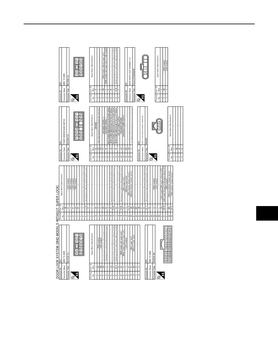
DOOR & LOCK SYSTEM
DLK-545
< WIRING DIAGRAM >
[TYPE 4]
C
D
E
F
G
H
I
J
L
M
A
B
DLK
N
O
P
JRKWE3990GB
|
|
|
DOOR & LOCK SYSTEM DLK-545 < WIRING DIAGRAM > [TYPE 4] C D E F G H I J L M A B DLK N O P JRKWE3990GB |