Qashqai J11. Engine control system (MR20DD) - part 17


  Index      Nissan     Qashqai J11. Engine control system (MR20DD). Service and Repair Manual


Search            copyright infringement  


Content      ..     15      16      17      18     ..


Qashqai J11. Engine control system (MR20DD) - part 17


ECM-258

< DTC/CIRCUIT DIAGNOSIS >

[MR20DD]

P0327, P0328 KS

2.

CHECK KNOCK SENSOR INPUT SIGNAL CIRCUIT FOR OPEN AND SHORT

1.

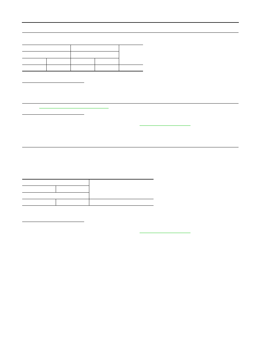
Check the continuity between knock sensor harness connector and ECM harness connector.

2.

Also check harness for short to ground and short to power.

Is the inspection result normal?

YES

>> GO TO 3.

NO

>> Repair or replace malfunctioning part.

3.

CHECK KNOCK SENSOR

Refer to 

ECM-258, "Component Inspection"

.

Is the inspection result normal?

YES

>> INSPECTION END

NO

>> Replace malfunctioning knock sensor. Refer to 

EM-222, "Exploded View"

.

Component Inspection

INFOID:0000000010702957

1.

CHECK KNOCK SENSOR

1.

Turn ignition switch OFF.

2.

Disconnect knock sensor harness connector.

3.

Check resistance between knock sensor terminals as follows.
NOTE:
It is necessary to use an ohmmeter which can measure more than 10 M

.

CAUTION:

Do not use any knock sensors that have been dropped or physically damaged. Use only new ones.

Is the inspection result normal?

YES

>> INSPECTION END

NO

>> Replace malfunctioning knock sensor. Refer to 

EM-222, "Exploded View"

.

+

Continuity

Knock sensor

ECM

Connector

Terminal

Connector

Terminal

F153

1

F15

40

Existed

Knock sensor

Resistance

+

Terminal

1

2

Approx. 532 - 588 k

 [at 20

°

C (68

°

F)]

P0335 CKP SENSOR

ECM-259

< DTC/CIRCUIT DIAGNOSIS >

[MR20DD]

C

D

E

F

G

H

I

J

K

L

M

A

ECM

N

P

O

P0335 CKP SENSOR

DTC Description

INFOID:0000000010702958

DTC DETECTION LOGIC

POSSIBLE CAUSE

• Harness or connectors [Crankshaft position sensor (POS) circuit is open or shorted.]
• Crankshaft position sensor (POS)
• Signal plate

FAIL-SAFE

DTC CONFIRMATION PROCEDURE

1.

CHECK DTC PRIORITY

If DTC P0335 is displayed with DTC P0643, first perform the trouble diagnosis for DTC P0643.

Is applicable DTC detected?

YES

>> Perform diagnosis of applicable. Refer to 

ECM-306, "DTC Description"

.

NO

>> GO TO 2.

2.

PRECONDITIONING

If DTC Confirmation Procedure has been previously conducted, always turn ignition switch OFF and wait at
least 10 seconds before conducting the next test.
TESTING CONDITION:
Before performing the following procedure, confirm that battery voltage is more than 10.5 V at idle.

>> GO TO 3.

3.

PERFORM DTC CONFIRMATION PROCEDURE

1.

Start engine and let it idle for at least 5 seconds.
If engine does not start, crank engine for at least 2 seconds.

2.

Check 1st trip DTC.

Is 1st trip DTC detected?

YES

>> Proceed to 

ECM-259, "Diagnosis Procedure"

.

NO-1

>> To check malfunction symptom before repair: Refer to 

GI-41, "Intermittent Incident"

.

NO-2

>> Confirmation after repair: INSPECTION END

Diagnosis Procedure

INFOID:0000000010702959

1.

CHECK DTC PRIORITY

If DTC P0335 is displayed with DTC P0643, first perform the trouble diagnosis for DTC P0643.

Is applicable DTC detected?

YES

>> Perform diagnosis of applicable. Refer to 

ECM-306, "DTC Description"

.

DTC No.

CONSULT screen terms

(Trouble diagnosis content)

DTC detecting condition

P0335

CKP SEN/CIRCUIT
(Crankshaft position sensor “A” circuit)

• The crankshaft position sensor (POS) signal is not detected by the ECM 

during the first few seconds of engine cranking.

• The proper pulse signal from the crankshaft position sensor (POS) is not 

sent to ECM while the engine is running.

Engine operating condition in fail-safe mode

Fail safe mode

Vehicle behavior

Device fix mode

• This mode fixes the IVT control solenoid valve and the EVT control solenoid valve in the refer-

ence position.

• The intake manifold runner control valve motor is turned OFF (intake manifold runner control 

valve opens).

ECM-260

< DTC/CIRCUIT DIAGNOSIS >

[MR20DD]

P0335 CKP SENSOR

NO

>> GO TO 2.

2.

CHECK CKP SENSOR (POS) POWER SUPPLY CIRCUIT-1

1.

Turn ignition switch OFF.

2.

Disconnect crankshaft position (CKP) sensor (POS) harness connector.

3.

Turn ignition switch ON.

4.

Check the voltage between CKP sensor (POS) harness connector and ground.

Is the inspection result normal?

YES

>> GO TO 3.

NO

>> GO TO 6.

3.

CHECK CKP SENSOR (POS) INPUT SIGNAL CIRCUIT FOR OPEN AND SHORT

1.

Turn ignition switch OFF.

2.

Disconnect ECM harness connector.

3.

Check the continuity between CKP sensor (POS) harness connector and ECM harness connector.

4.

Also check harness for short to ground and short to power.

Is the inspection result normal?

YES

>> GO TO 4.

NO

>> Repair or replace malfunctioning part.

4.

CHECK CKP SENSOR (POS)

Refer to 

ECM-261, "Component Inspection"

.

Is the inspection result normal?

YES

>> GO TO 5.

NO

>> Replace crankshaft position sensor (POS). Refer to 

EM-222, "Exploded View"

.

5.

CHECK GEAR TOOTH

1.

Remove crankshaft position sensor (POS). Refer to 

EM-222, "Exploded View"

.

2.

Look into the mounting hole 

 of the crankshaft position sensor

(POS) to check that there is no missing gear tooth in the signal
plate .

Is the inspection result normal?

YES

>> INSPECTION END

NO

>> Replace the signal plate. Refer to 

EM-181, "Exploded View"

.

CKP sensor (POS)

Condition

Voltage

Connector

+

Terminal

F85

1

2

Ignition switch: ON

Approx. 5 V

Ignition switch: OFF

Approx. 0 V

+

Continuity

CKP sensor (POS)

ECM

Connector

Terminal

Connector

Terminal

F85

3

F15

48

Existed

JPBIA4623ZZ

P0335 CKP SENSOR

ECM-261

< DTC/CIRCUIT DIAGNOSIS >

[MR20DD]

C

D

E

F

G

H

I

J

K

L

M

A

ECM

N

P

O

6.

CHECK CKP SENSOR (POS) POWER SUPPLY CIRCUIT-2

Check the voltage between CKP sensor (POS) harness connector and ground.

Is the inspection result normal?

YES

>> GO TO 7.

NO

>> GO TO 8.

7.

CHECK CKP SENSOR (POS) GROUND CIRCUIT FOR OPEN AND SHORT

1.

Turn ignition switch OFF.

2.

Disconnect ECM harness connector.

3.

Check the continuity between CKP sensor (POS) harness connector and ECM harness connector.

Is the inspection result normal?

YES

>> INSPECTION END

NO

>> Repair or replace malfunctioning part.

8.

CHECK CKP SENSOR (POS) POWER SUPPLY CIRCUIT-3

1.

Turn ignition switch OFF.

2.

Disconnect ECM harness connector.

3.

Check the continuity between CKP sensor (POS) harness connector and ECM harness connector.

Is the inspection result normal?

YES

>> INSPECTION END

NO

>> Repair or replace malfunctioning part.

Component Inspection

INFOID:0000000010702960

1.

CHECK CRANKSHAFT POSITION SENSOR (POS)-1

1.

Turn ignition switch OFF.

2.

Loosen the fixing bolt of the sensor.

3.

Disconnect crankshaft position sensor (POS) harness connector.

4.

Remove the sensor.

+

Ground

Condition

Voltage

CKP sensor (POS)

Connector

Terminal

F85

1

Ground

Ignition switch: ON

Approx. 5 V

Ignition switch: OFF

Approx. 0 V

+

Continuity

CKP sensor (POS)

ECM

Connector

Terminal

Connector

Terminal

F85

2

F15

44

Existed

+

Continuity

CKP sensor (POS)

ECM

Connector

Terminal

Connector

Terminal

F85

1

F15

21

Existed

ECM-262

< DTC/CIRCUIT DIAGNOSIS >

[MR20DD]

P0335 CKP SENSOR

5.

Visually check the sensor for chipping.

Is the inspection result normal?

YES

>> GO TO 2.

NO

>> Replace crankshaft position sensor (POS). Refer to 

EM-

222, "Exploded View"

.

2.

CHECK CRANKSHAFT POSITION SENSOR (POS)-2

Check resistance between crankshaft position sensor (POS) terminals as follows.

Is the inspection result normal?

YES

>> GO TO 3.

NO

>> Replace crankshaft position sensor (POS). Refer to 

EM-222, "Exploded View"

.

3.

CHECK CRANKSHAFT POSITION SENSOR (POS)-3

1.

Reconnect crankshaft position sensor (POS) harness connector.

2.

Turn ignition switch ON.

3.

As shown in the figure, check the voltage between ECM termi-
nals under following conditions with metal bar such as screw
driver .
NOTE:
Use the metal bar which is not magnetized.

CAUTION:

Do not give a shock to the sensor tip.

Is the inspection result normal?

YES

>> INSPECTION END

NO

>> Replace crankshaft position sensor (POS) 1. Refer to  

EM-222, "Exploded View"

.

PBIA9210J

CKP sensor (POS)

Resistance

+

Terminal

1

2

Except 0 

 [at 25

°

C (77

°

F)]

3

2

3

JMBIA0285ZZ

ECM

Condition

Voltage

Connector

+

Terminal

F15

48

44

When moves the metal bar to 
the direction of sensor's normal 
rotation

0 - 1 V

When moves the metal bar to 
the direction of sensor's re-
versed rotation

4 - 5 V

P0340 CMP SENSOR

ECM-263

< DTC/CIRCUIT DIAGNOSIS >

[MR20DD]

C

D

E

F

G

H

I

J

K

L

M

A

ECM

N

P

O

P0340 CMP SENSOR

DTC Description

INFOID:0000000010702961

DTC DETECTION LOGIC

POSSIBLE CAUSE

• Harness or connectors
- The camshaft position sensor circuit is open or shorted.
- Sensor power supply circuit 2 is shorted.
• Camshaft position sensor (PHASE)
• Exhaust valve timing control position sensor
• Camshaft (INT)
• Camshaft (EXT)
• Starter motor
• Starting system circuit
• Dead (Weak) battery
• Sensor power supply circuit 2 sensor

FAIL-SAFE

DTC CONFIRMATION PROCEDURE

1.

PRECONDITIONING

If DTC Confirmation Procedure has been previously conducted, always turn ignition switch OFF and wait at
least 10 seconds before conducting the next test.
TESTING CONDITION:
Before performing the following procedure, confirm that battery voltage is more than 10.5 V at idle.

>> GO TO 2.

2.

DTC CONFIRMATION PROCEDURE-1

1.

Start engine and let it idle for at least 5 seconds.
If engine does not start, crank engine for at least 2 seconds.

2.

Check 1st trip DTC.

Is 1st trip DTC detected?

YES

>> Proceed to 

ECM-264, "Diagnosis Procedure"

.

NO

>> GO TO 3.

3.

DTC CONFIRMATION PROCEDURE-2

1.

Maintaining engine speed at more than 800 rpm for at least 5 seconds.

2.

Check 1st trip DTC.

Is 1st trip DTC detected?

YES

>> Proceed to 

ECM-264, "Diagnosis Procedure"

.

NO-1

>> To check malfunction symptom before repair: Refer to 

GI-41, "Intermittent Incident"

.

DTC No.

CONSULT screen terms

(Trouble diagnosis content)

DTC detecting condition

P0340

CMP SEN/CIRC-B1
(Camshaft position sensor “A” circuit bank 1 
or single sensor)

• The cylinder No. signal is not sent to ECM for the first few seconds during 

engine cranking.

• The cylinder No. signal is not sent to ECM during engine running.
• The cylinder No. signal is not in the normal pattern during engine running.

Engine operating condition in fail-safe mode

Fail safe mode

Vehicle behavior

Device fix mode

• This mode fixes the IVT control solenoid valve and the EVT control solenoid valve in the refer-

ence position.

• The intake manifold runner control valve motor is turned OFF (intake manifold runner control 

valve opens).

ECM-264

< DTC/CIRCUIT DIAGNOSIS >

[MR20DD]

P0340 CMP SENSOR

NO-2

>> Confirmation after repair: INSPECTION END

Diagnosis Procedure

INFOID:0000000010702962

1.

CHECK STARTING SYSTEM

Turn ignition switch to START position.

Does the engine turn over? Does the starter motor operate?

YES

>> GO TO 2.

NO

>> Check starting system. Refer to 

STR-18, "Work Flow"

.

2.

CHECK CMP SENSOR (PHASE) POWER SUPPLY CIRCUIT-1

1.

Turn ignition switch OFF.

2.

Disconnect camshaft position (CMP) sensor (PHASE) harness connector. 

3.

Turn ignition switch ON.

4.

Check the voltage between CMP sensor (PHASE) harness connector terminals.

Is the inspection result normal?

YES

>> GO TO 8.

NO

>> GO TO 3.

3.

CHECK CMP SENSOR (PHASE) POWER SUPPLY CIRCUIT-2

Check the voltage between CMP sensor (PHASE) harness connector and ground.

Is the inspection result normal?

YES

>> GO TO 6.

NO

>> GO TO 4.

4.

CHECK CMP SENSOR (PHASE) POWER SUPPLY CIRCUIT-3

1.

Turn ignition switch OFF.

2.

Disconnect ECM harness connector. 

3.

Check the continuity between CMP sensor (PHASE) harness connector and ECM harness connector. 

Is the inspection result normal?

YES

>> GO TO 5.

NO

>> Repair or replace malfunctioning part.

5.

CHECK CMP SENSOR (PHASE) POWER SUPPLY CIRCUIT-4

Refer to 

ECM-392, "Diagnosis Procedure"

.

Is the inspection result normal?

YES

>> INSPECTION END

NO

>> Replace malfunctioning part.

CMP sensor (PHASE)

Voltage

Connector

+

Terminal

F37

1

2

Approx. 5 V

+

Ground

Voltage

CMP sensor (PHASE)

Connector

Terminal

F37

1

Ground

Approx. 5 V

+

Continuity

CMP sensor (PHASE)

ECM

Connector

Terminal

Connector

Terminal

F37

1

F15

43

Existed

P0340 CMP SENSOR

ECM-265

< DTC/CIRCUIT DIAGNOSIS >

[MR20DD]

C

D

E

F

G

H

I

J

K

L

M

A

ECM

N

P

O

6.

CHECK CMP SENSOR (PHASE) GROUND CIRCUIT FOR OPEN AND SHORT

1.

Turn ignition switch OFF.

2.

Disconnect ECM harness connector. 

3.

Check the continuity between CMP sensor (PHASE) harness connector and ECM harness connector. 

4.

Also check harness for short to ground and short to power.

Is the inspection result normal?

YES

>> GO TO 7.

NO

>> Repair or replace malfunctioning part.

7.

CHECK ECM GROUND CIRCUIT FOR OPEN AND SHORT

Check the continuity between ECM harness connector and ground.

Is the inspection result normal?

YES

>> INSPECTION END

NO

>> Repair or replace malfunctioning part.

8.

CHECK CMP SENSOR (PHASE) INPUT SIGNAL CIRCUIT FOR OPEN AND SHORT

1.

Check the continuity between CMP sensor (PHASE) harness connector and ECM harness connector.

2.

Also check harness for short to ground and short to power.

Is the inspection result normal?

YES

>> GO TO 9.

NO

>> Repair or replace malfunctioning part.

9.

CHECK CAMSHAFT POSITION SENSOR (PHASE)

Refer to 

ECM-266, "Component Inspection"

.

Is the inspection result normal?

YES

>> GO TO 10.

NO

>> Replace camshaft position sensor (PHASE). Refer to 

EM-196, "Exploded View"

.

10.

CHECK CAMSHAFT (INT)

Check the following.

+

Continuity

CMP sensor (PHASE)

ECM

Connector

Terminal

Connector

Terminal

F37

2

F15

15

Existed

+

Ground

Continuity

ECM

Connector

Terminal

F15

11

Ground

Existed

E57

123

125

128

+

Continuity

CMP sensor (PHASE)

ECM

Connector

Terminal

Connector

Terminal

F37

3

F15

19

Existed

ECM-266

< DTC/CIRCUIT DIAGNOSIS >

[MR20DD]

P0340 CMP SENSOR

• Accumulation of debris to the signal plate of camshaft rear end
• Chipping signal plate of camshaft rear end
Is the inspection result normal?

YES

>> INSPECTION END

NO

>> Remove debris and clean the signal plate of camshaft

rear end or replace camshaft. Refer to 

EM-197,

"Removal and Installation"

.

Component Inspection

INFOID:0000000010702963

1.

CHECK CAMSHAFT POSITION SENSOR (PHASE)-1

1.

Turn ignition switch OFF.

2.

Loosen the fixing bolt of the sensor.

3.

Disconnect camshaft position sensor (PHASE) harness connector.

4.

Remove the sensor.

5.

Visually check the sensor for chipping.

Is the inspection result normal?

YES

>> GO TO 2.

NO

>> Replace camshaft position sensor (PHASE). Refer to

EM-196, "Exploded View"

.

2.

CHECK CAMSHAFT POSITION SENSOR (PHASE)-2

Check resistance camshaft position sensor (PHASE) terminals as follows.

Is the inspection result normal?

YES

>> INSPECTION END

NO

>> Replace camshaft position sensor (PHASE). Refer to 

EM-196, "Exploded View"

.

JSBIA0599ZZ

PBIA9876J

CMP sensor (PHASE)

Resistance

+

Terminal

1

2

Except 0 

 [at 25

°

C (77

°

F)]

3

2

3

P0365 EXHAUST VALVE TIMING CONTROL POSITION SENSOR

ECM-267

< DTC/CIRCUIT DIAGNOSIS >

[MR20DD]

C

D

E

F

G

H

I

J

K

L

M

A

ECM

N

P

O

P0365 EXHAUST VALVE TIMING CONTROL POSITION SENSOR

DTC Description

INFOID:0000000010702964

DTC DETECTION LOGIC

Possible Cause

• Harness or connectors
- Exhaust valve timing control position sensor circuit is open or shorted.
- Sensor power supply 2 circuit is shorted.
• Exhaust valve timing control position sensor
• Exhaust  camshaft
• Starter motor
• Starting circuit
• Battery deterioration
• Sensor power supply 1 circuit sensors

FAIL-SAFE

DTC CONFIRMATION PROCEDURE

1.

PRECONDITIONING

If DTC Confirmation Procedure has been previously conducted, always perform the following procedure
before conducting the next test.
1.

Turn ignition switch OFF and wait at least 10 seconds.

2.

Turn ignition switch ON.

3.

Turn ignition switch OFF and wait at least 10 seconds.

TESTING CONDITION: 
Before performing the following procedure, confirm that battery voltage is more than 10.5 V at idling.

>> GO TO 2.

2.

PERFORM DTC CONFIRMATION PROCEDURE-1

1.

Start engine and let it idle for at least 5 seconds.
If engine does not start, crank engine for at least 2 seconds.

2.

Check 1st trip DTC.

Is 1st trip DTC detected?

YES

>> Proceed to 

ECM-268, "Diagnosis Procedure"

.

NO

>> GO TO 3.

3.

PERFORM DTC CONFIRMATION PROCEDURE-2

1.

Keep the engine speed at more than 800 rpm for at least 5 seconds.

2.

Check 1st trip DTC.

DTC No.

CONSULT screen terms

(Trouble diagnosis content)

DTC detecting condition

P0365

CMP SEN/CIRC-B1
(Camshaft position sensor circuit bank 1)

• EVT control position sensor signal is not sent to ECM 

during engine cranking.

• EVT control position sensor signal is not sent to ECM 

during engine running.

• The pulse signal sent from the EVT control position sen-

sor to ECM is not in the normal pattern during engine 
running.

Engine operating condition in fail-safe mode

Fail safe mode

Vehicle behavior

Device fix mode

• This mode fixes the IVT control solenoid valve and the EVT control solenoid valve in the refer-

ence position.

• The intake manifold runner control valve motor is turned OFF (intake manifold runner control 

valve opens).

ECM-268

< DTC/CIRCUIT DIAGNOSIS >

[MR20DD]

P0365 EXHAUST VALVE TIMING CONTROL POSITION SENSOR

Is 1st trip DTC detected?

YES

>> Proceed to 

ECM-268, "Diagnosis Procedure"

.

NO-1

>> To check malfunction symptom before repair: Refer to

GI-41, "Intermittent Incident"

.

NO-2

>> Confirmation after repair: INSPECTION END

Diagnosis Procedure

INFOID:0000000010702965

1.

CHECK STARTING SYSTEM

Turn ignition switch to START position.

Does the engine turn over? Does the starter motor operate?

YES

>> GO TO 2.

NO

>> Check starting system. Refer to 

STR-18, "Work Flow"

.

2.

CHECK EXHAUST VALVE TIMING (EVT) CONTROL POSITION SENSOR POWER SUPPLY CIRCUIT-1

1.

Turn ignition switch OFF.

2.

Disconnect exhaust valve timing (EVT) control position sensor harness connector.

3.

Turn ignition switch ON.

4.

Check the voltage between EVT control position sensor harness connector terminals.

Is the inspection result normal?

YES

>> GO TO 8.

NO

>> GO TO 3.

3.

CHECK EXHAUST VALVE TIMING (EVT) CONTROL POSITION SENSOR POWER SUPPLY CIRCUIT-2

Check the voltage between EVT control position sensor harness connector and ground.

Is the inspection result normal?

YES

>> GO TO 6.

NO

>> GO TO 4.

4.

CHECK EXHAUST VALVE TIMING (EVT) CONTROL POSITION SENSOR POWER SUPPLY CIRCUIT-3

1.

Turn ignition switch OFF.

2.

Disconnect ECM harness connector.

3.

Check the continuity between EVT control position sensor harness connector and ECM harness connec-
tor.

Is the inspection result normal?

YES

>> GO TO 5.

NO

>> Repair or replace error-detected parts.

5.

CHECK SENSOR POWER SUPPLY 1 CIRCUIT

EVT control position sensor

Voltage

(Approx.)

Connector

+

Terminals

F36

1

2

5 V

+

Voltage

(Approx.)

EVT control position sensor

Connector

Terminal

F36

1

Ground

5 V

+

Continuity

EVT control position sensor

ECM

Connector

Terminal

Connector

Terminal

F36

1

F15

24

Existed

P0365 EXHAUST VALVE TIMING CONTROL POSITION SENSOR

ECM-269

< DTC/CIRCUIT DIAGNOSIS >

[MR20DD]

C

D

E

F

G

H

I

J

K

L

M

A

ECM

N

P

O

Refer to 

ECM-307, "Diagnosis Procedure"

.

Is the inspection result normal?

YES

>> INSPECTION END

NO

>> Replace malfunctioning parts.

6.

CHECK EVT CONTROL POSITION SENSOR GROUND CIRCUIT

1.

Turn ignition switch OFF.

2.

Disconnect ECM harness connector.

3.

Check the continuity between EVT control position sensor harness connector and ECM harness connec-
tor.

4.

Also check harness for short to power.

Is the inspection result normal?

YES

>> GO TO 7.

NO

>> Repair or replace error-detected parts.

7.

CHECK ECM GROUND CIRCUIT

Check the continuity between ECM harness connector and ground.

Is the inspection result normal?

YES

>> INSPECTION END

NO

>> Repair or replace error-detected parts.

8.

CHECK EVT CONTROL POSITION SENSOR INPUT SIGNAL CIRCUIT

1.

Check the continuity between EVT control position sensor harness connector and ECM harness connec-
tor.

2.

Also check harness for short to power.

Is the inspection result normal?

YES

>> GO TO 9.

NO

>> Repair or replace error-detected parts.

9.

CHECK EVT CONTROL POSITION SENSOR

Refer to 

ECM-270, "Component Inspection"

.

Is the inspection result normal?

YES

>> GO TO 10.

NO

>> Replace EVT control position sensor. Refer to 

EM-196, "Exploded View"

.

+

Continuity

EVT control position sensor

ECM

Connector

Terminal

Connector

Terminal

F36

2

F15

42

Existed

+

Continuity

ECM

Connector

Terminal

F15

11

Ground

Existed

E57

123

125

128

+

Continuity

EVT control position sensor

ECM

Connector

Terminal

Connector

Terminal

F36

3

F15

46

Existed

ECM-270

< DTC/CIRCUIT DIAGNOSIS >

[MR20DD]

P0365 EXHAUST VALVE TIMING CONTROL POSITION SENSOR

10.

CHECK CAMSHAFT (EXT)

Check the following.
• Accumulation of debris to the signal plate of camshaft rear end
• Chipping signal plate of camshaft rear end

Is the inspection result normal?

YES

>> INSPECTION END

NO

>> Remove debris and clean the signal plate of camshaft

rear end or replace camshaft. Refer to 

EM-197,

"Removal and Installation"

.

Component Inspection

INFOID:0000000010702966

1.

EXHAUST VALVE TIMING (EVT) CONTROL POSITION SENSOR-1

1.

Turn ignition switch OFF.

2.

Loosen the sensor mounting bolt.

3.

Disconnect the EVT control position sensor harness connector.

4.

Remove the EVT control position sensor.

5.

Visually check the sensor for chipping.

Is the inspection result normal?

YES

>> GO TO 2.

NO

>> Replace the EVT control position sensor. Refer to 

EM-

196, "Exploded View"

.

2.

EXHAUST VALVE TIMING (EVT) CONTROL POSITION SENSOR-2

Check resistance between EVT control position sensor terminals as shown below.

Is the inspection result normal?

YES

>> INSPECTION END

NO

>> Replace the EVT control position sensor. Refer to 

EM-196, "Exploded View"

.

JSBIA0599ZZ

PBIA9876J

EVT control position sensor

Resistance

+

Terminals

1

2

Except 0 

 [at 25

°

C (77

°

F)]

3

2

3

P0420 THREE WAY CATALYST FUNCTION

ECM-271

< DTC/CIRCUIT DIAGNOSIS >

[MR20DD]

C

D

E

F

G

H

I

J

K

L

M

A

ECM

N

P

O

P0420 THREE WAY CATALYST FUNCTION

DTC Description

INFOID:0000000010702967

DTC DETECTION LOGIC

The ECM monitors the switching frequency ratio of air fuel ratio (A/F)
sensor 1 and heated oxygen sensor 2.
A three way catalyst (manifold) with high oxygen storage capacity
will indicate a low switching frequency of heated oxygen sensor 2.
As oxygen storage capacity decreases, the heated oxygen sensor 2
switching frequency will increase.
When the frequency ratio of air fuel ratio (A/F) sensor 1 and heated
oxygen sensor 2 approaches a specified limit value, the three way
catalyst (manifold) malfunction is diagnosed.

POSSIBLE CAUSE

• Three way catalyst (manifold)
• Exhaust tube
• Intake air leaks
• Exhaust air leaks
• Fuel injector
• Fuel injector leaks
• Spark plug
• Improper ignition timing

FAIL-SAFE

Not applicable

DTC CONFIRMATION PROCEDURE

1.

PRECONDITIONING

If DTC Confirmation Procedure has been previously conducted, always perform the following procedure
before conducting the next test.
TESTING CONDITION:
Do not hold engine speed for more than the specified minutes below.
1.

Turn ignition switch OFF and wait at least 10 seconds.

2.

Turn ignition switch ON.

3.

Turn ignition switch OFF and wait at least 10 seconds.

Will CONSULT be used?

YES

>> GO TO 2.

NO

>> GO TO 5.

2.

PERFORM DTC CONFIRMATION PROCEDURE-1

With CONSULT

1.

Turn ignition switch ON and select “DATA MONITOR” mode of “ENGINE” using CONSULT.

2.

Start engine and warm it up to the normal operating temperature.

3.

Turn ignition switch OFF and wait at least 10 seconds.

4.

Start engine and keep the engine speed between 3,500 and 4,000 rpm for at least 1 minute under no load.

5.

Let engine idle for 1 minute.

6.

Check that “COOLAN TEMP/S” indicates more than 70

°

C (158

°

F).

If not, warm up engine and go to next step when “COOLAN TEMP/S” indication reaches to 70

°

C (158

°

F).

SEF484YB

DTC No.

CONSULT screen terms

(Trouble diagnosis content)

DTC detecting condition

P0420

TW CATALYST SYS-B1
(Catalyst system efficiency below threshold 
bank 1)

• Three way catalyst (manifold) does not operate properly.
• Three way catalyst (manifold) does not have enough oxygen storage ca-

pacity.

ECM-272

< DTC/CIRCUIT DIAGNOSIS >

[MR20DD]

P0420 THREE WAY CATALYST FUNCTION

7.

Open engine hood.

8.

Select “DTC & SRT CONFIRMATION” then “SRT WORK SUPPORT” mode of “ENGINE” using CON-
SULT.

9.

Rev engine up to 2,000 to 3,000 rpm and hold it for 3 consecutive minutes then release the accelerator
pedal completely.

10. Check the indication of “CATALYST”.

Which is displayed on CONSULT screen?

CMPLT >> GO TO 4.
INCMP >> GO TO 3.

3.

PERFORM DTC CONFIRMATION PROCEDURE-2

1.

Wait 5 seconds at idle.

2.

Rev engine up to 2,000 to 3,000 rpm and maintain it until “INCMP” of “CATALYST” changes to “CMPLT”.
NOTE:
It will take approximately 5 minutes.
If “CMPLT” is not displayed after 5 minutes, turn ignition switch OFF and cool down the engine. Retry from
step 1 when “COOLAN TEMP/S” indication reaches to 70

°

C (158

°

F).

Does the indication change to “CMPLT”

YES

>> GO TO 4.

NO

>> GO TO 2.

4.

PERFORM DTC CONFIRMATION PROCEDURE-3

Check 1st trip DTC.

Is 1st trip DTC detected?

YES

>> Proceed to 

ECM-272, "Diagnosis Procedure"

.

NO-1

>> To check malfunction symptom before repair: Refer to 

GI-41, "Intermittent Incident"

.

NO-2

>> Confirmation after repair: INSPECTION END

5.

PERFORM COMPONENT FUNCTION CHECK

Without CONSULT

NOTE:
Use component function check to check the overall function of the three way catalyst (manifold). During this
check, a 1st trip DTC might not be confirmed.
1.

Start engine and warm it up to the normal operating temperature.

2.

Turn ignition switch OFF and wait at least 10 seconds.

3.

Restart engine and keep the engine speed between 3,500 and 4,000 rpm for at least 1 minute under no
load.

4.

Let engine idle for 1 minute.

5.

Open engine hood.

6.

Check the voltage between ECM harness connector terminals as per the following condition.

Is the inspection result normal?

YES-1 >> To check malfunction symptom before repair: Refer to 

GI-41, "Intermittent Incident"

.

YES-2 >> Confirmation after repair: INSPECTION END
NO

>> Proceed to 

ECM-272, "Diagnosis Procedure"

.

Diagnosis Procedure

INFOID:0000000010702968

1.

CHECK EXHAUST SYSTEM

Visually check exhaust tubes, three way catalyst and muffler for dent.

ECM

Condition

Voltage (V)

Connector

+

Terminal

F16

57

59

Keeping engine speed at 2500 
rpm constant under no load

The voltage fluctuation cycle takes 
more than 5 seconds.
1 cycle : 0.6 - 1.0 V 

 0 - 0.3 V 

 0.6 

- 1.0 V

P0420 THREE WAY CATALYST FUNCTION

ECM-273

< DTC/CIRCUIT DIAGNOSIS >

[MR20DD]

C

D

E

F

G

H

I

J

K

L

M

A

ECM

N

P

O

Is the inspection result normal?

YES

>> GO TO 2.

NO

>> Repair or replace error-detected parts. Refer to 

EX-11, "Exploded View"

.

2.

CHECK EXHAUST GAS LEAK

1.

Start engine and run it at idle.

2.

Listen for an exhaust gas leak before the three way catalyst (manifold).

Is the inspection result normal?

YES

>> GO TO 3.

NO

>> Repair or replace error-detected parts. Refer to 

EX-11, "Exploded View"

.

3.

CHECK INTAKE AIR LEAK AND PCV HOSE

1.

Start engine and let it idle.

2.

Listen for an intake air leak after the mass air flow sensor.

Is the inspection result normal?

YES

>> GO TO 4.

NO

>> Repair or replace error-detected parts. Refer to 

EX-11, "Exploded View"

.

4.

CHECK IGNITION TIMING AND IDLE SPEED

Check the following items. Refer to 

ECM-132, "Work Procedure"

.

For specification, refer to 

ECM-417, "Ignition Timing"

For specification, refer to 

ECM-417, "Idle Speed"

.

Is the inspection result normal?

YES

>> GO TO 5.

NO

>> Follow the 

ECM-132, "Work Procedure"

.

5.

CHECK FUEL INJECTOR

Check the fuel injector. Refer to 

ECM-372, "Component Function Check"

.

Is the inspection result normal?

YES

>> GO TO 6.

NO

>> Perform 

ECM-372, "Diagnosis Procedure"

.

6.

CHECK FUNCTION OF IGNITION COIL-1

CAUTION:

Do the following procedure in the place where ventilation is good without the combustible.
1.

Turn ignition switch OFF.

2.

Remove fuel pump fuse in IPDM E/R to release fuel pressure.
NOTE:
Do not use CONSULT to release fuel pressure, or fuel pressure applies again during the following proce-
dure.

3.

Start engine.

4.

After engine stalls, crank it two or three times to release all fuel pressure

5.

Turn ignition switch OFF.

6.

Remove all ignition coil harness connectors to avoid the electrical discharge from the ignition coils.

1:

Three way catalyst

2:

A/F sensor 1

3:

HO2S2

4:

Muffler

PBID0288J


Content      ..     15      16      17      18     ..