Qashqai J11. Engine control system (K9K) - part 16


  Index      Nissan     Qashqai J11. Engine control system (K9K). Service and Repair Manual


Search            copyright infringement  


Content      ..     14      15      16      17     ..


Qashqai J11. Engine control system (K9K) - part 16


P0409 EGR VOLUME CONTROL VALVE POSITION SENSOR

ECK-241

< DTC/CIRCUIT DIAGNOSIS >

[K9K]

C

D

E

F

G

H

I

J

K

L

M

A

ECK

N

P

O

2.

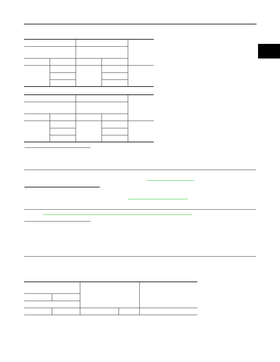
Check low pressure EGR valve and high pressure EGR valve position sensor circuit for open and short.

HIGH PRESSURE EGR VOLUME CONTROL VALVE

LOW PRESSURE EGR VOLUME CONTROL VALVE

Is the inspection result normal?

YES

>> GO TO 5.

NO

>> Repair or replace error-detected parts.

5.

DTC CONFIRMATION PROCEDURE

1.

Erase DTC.

2.

Perform DTC confirmation procedure again. Refer to 

ECK-240, "DTC Logic"

.

Is the DTC P0409 displayed again?

YES

>> GO TO 6.

NO

>> Check intermittent incident. Refer to 

GI-41, "Intermittent Incident"

.

6.

CHECK LOW PRESSURE EGR VALVE MOTOR AND HIGH PRESSURE EGR VALVE MOTOR

Refer to 

ECK-241, "Component Inspection (EGR Volume Control Valve Motor)"

.

Is the inspection result normal?

YES

>> Replace high pressure EGR valve position sensor and low pressure EGR valve position sensor.

NO

>> Replace error-detected parts. 

Component Inspection (EGR Volume Control Valve Motor)

INFOID:0000000010289829

1.

CHECK LOW PRESSURE EGR VALVE MOTOR AND HIGH PRESSURE EGR VALVE MOTOR

1.

Turn ignition switch OFF.

2.

Disconnect low pressure EGR valve and high pressure EGR valve harness connector.

3.

Check resistance between low pressure EGR valve and high pressure EGR valve terminals as follows.

HIGH PRESSURE EGR VOLUME CONTROL VALVE

+

-

Continuity

ECM

High pressure EGR volume 

control valve

Connector

Terminal

Connector

Terminal

F80

69

F60

6

Existed

70

3

75

1

+

-

Continuity

ECM

Low pressure EGR volume 

control valve

Connector

Terminal

Connector

Terminal

F80

65

F34

1

Existed

66

2

79

3

High pressure EGR volume 

control valve

Condition

Resistance (Approx.)

+

-

Terminal

2

5

Temperature 

°

C (

°

F)

23 (73)

2.4 

ECK-242

< DTC/CIRCUIT DIAGNOSIS >

[K9K]

P0409 EGR VOLUME CONTROL VALVE POSITION SENSOR

LOW PRESSURE EGR VOLUME CONTROL VALVE

Is the inspection result normal?

YES

>> INSPECTION END

NO

>> Replace low pressure EGR valve or high pressure EGR valve.

Low pressure EGR volume 

control valve

Condition

Resistance (Approx.)

+

-

Terminal

5

6

Temperature 

°

C (

°

F)

20 (68)

1.69 

P0470 EXHAUST GAS PRESSURE SENSOR

ECK-243

< DTC/CIRCUIT DIAGNOSIS >

[K9K]

C

D

E

F

G

H

I

J

K

L

M

A

ECK

N

P

O

P0470 EXHAUST GAS PRESSURE SENSOR

DTC Logic

INFOID:0000000010289830

DTC DETECTION LOGIC

NOTE:
If DTC P0470 is displayed with DTC P0651, and P2263, perform the trouble diagnosis for DTC P0651,
and P2263. Refer to 

ECK-97, "DTC Index"

.

DTC CONFIRMATION PROCEDURE

1.

PRECONDITIONING

If DTC Confirmation Procedure has been previously conducted, always turn ignition switch OFF and wait at
least 1 minute before conducting the next test.

>> GO TO 2.

2.

PERFORM DTC CONFIRMATION PROCEDURE

1.

Turn ignition switch ON and wait at least 1 second.

2.

Check DTC.

Is DTC detected?

YES

>> Proceed to 

ECK-243, "Diagnosis Procedure"

.

NO

>> INSPECTION END

Diagnosis Procedure

INFOID:0000000010289831

1.

CHECK ECM HARNESS CONNECTOR CONNECTIONS

1.

Turn ignition switch OFF.

2.

Check ECM harness connector connection F80.

Is the inspection result normal?

YES

>> GO TO 2.

NO

>> Repair or replace error-detected parts.

2.

CHECK EXHAUST GAS PRESSURE SENSOR 1 HARNESS CONNECTOR CONNECTIONS

Check exhaust gas pressure sensor harness connector connection F110.

Is the inspection result normal?

YES

>> GO TO 3.

NO

>> Repair or replace error-detected parts.

3.

CHECK EXHAUST GAS PRESSURE SENSOR 1 POWER SUPPLY CIRCUIT

Check the power supply of the exhaust gas pressure sensor 1.

Is the inspection result normal?

DTC No.

CONSULT screen terms

(Trouble diagnosis content)

DTC detecting condition

Possible cause

P0470

TBN UPSTR PRS SEN CIRC
(Exhaust pressure sensor “A” circuit)
• 1.DEF: VOLTAGE TOO LOW
• 2.DEF: VOLTAGE TOO HIGH

• An excessively low voltage from the sensor is 

sent to ECM.

• An excessively high voltage from the sensor 

is sent to ECM.

• Exhaust gas pressure sensor 

1

• Turbocharger
• Exhaust manifold
• Exhaust  tube
• ECM

+

-

Continuity

Exhaust gas pressure sensor 1

Connector

Terminal

F110

3

Ground

Existed

ECK-244

< DTC/CIRCUIT DIAGNOSIS >

[K9K]

P0470 EXHAUST GAS PRESSURE SENSOR

YES

>> GO TO 4.

NO

>> Perform trouble diagnosis for power supply circuit.

4.

CHECK EXHAUST GAS PRESSURE SENSOR 1 CIRCUIT FOR OPEN AND SHORT

1.

Turn ignition switch OFF.

2.

Check exhaust gas pressure sensor 1 circuit for open and short.

Is the inspection result normal?

YES

>> GO TO 5.

NO

>> Repair or replace error-detected parts.

5.

CHECK EXHAUST GAS PRESSURE SENSOR 1

Refer to 

ECK-244, "Component Inspection (Exhaust Gas Pressure Sensor)"

.

Is the inspection result normal?

YES

>> GO TO 6.

NO

>> Replace error-detected parts.

6.

DTC CONFIRMATION PROCEDURES

1.

Erase DTC.

2.

Perform DTC confirmation procedure again. Refer to 

ECK-243, "DTC Logic"

.

Is the DTC P0470 displayed again?

YES

>> GO TO 7.

NO

>> Check intermittent incident. Refer to 

GI-41, "Intermittent Incident"

.

7.

CHECK TURBOCHARGER

Check turbocharger.

Is the inspection result normal?

YES

>> Check intermittent incident. Refer to 

GI-41, "Intermittent Incident"

.

NO

>> Repair or replace malfunctioning parts.

Component Inspection (Exhaust Gas Pressure Sensor)

INFOID:0000000010289832

1.

CHECK EXHAUST GAS PRESSURE SENSOR

1.

Disconnect exhaust gas pressure sensor harness connector.

2.

Check the resistance between exhaust gas pressure sensor terminals as follows.

Is the inspection result normal?

YES

>> INSPECTION END

NO

>> Replace exhaust gas pressure sensor.

+

-

Continuity

ECM

Exhaust gas pressure sen-

sor 1

Connector

Terminal

Connector

Terminal

F80

77

F110

3

Existed

78

1

83

2

Exhaust gas pressure sensor

Resistance (Approx.)

+

-

Terminal

2

1

100 k

P0471 EXHAUST GAS PRESSURE SENSOR 1

ECK-245

< DTC/CIRCUIT DIAGNOSIS >

[K9K]

C

D

E

F

G

H

I

J

K

L

M

A

ECK

N

P

O

P0471 EXHAUST GAS PRESSURE SENSOR 1

DTC Logic

INFOID:0000000010289833

DTC DETECTION LOGIC

NOTE:
If DTC P0471 is displayed with DTC P0335, P0470, and P2226, perform the trouble diagnosis for DTC
P0335, P0470, and P2226. Refer to 

ECK-97, "DTC Index"

.

DTC CONFIRMATION PROCEDURE

1.

PERFORM DIAGNOSIS PROCEDURE

NOTE:
DTC P0471 can not duplicate.

>> Proceed to 

ECK-245, "Diagnosis Procedure"

.

Diagnosis Procedure

INFOID:0000000010289834

1.

CHECK ECM HARNESS CONNECTOR CONNECTIONS

1.

Turn ignition switch OFF.

2.

Check ECM harness connector connection.

Is the inspection result normal?

YES

>> GO TO 2.

NO

>> Repair or replace error-detected parts.

2.

CHECK EXHAUST GAS PRESSURE SENSOR 1 HARNESS CONNECTOR CONNECTIONS

Check exhaust gas pressure sensor 1 harness connector connection.
Is the inspection result normal?

YES

>> GO TO 3.

NO

>> Repair or replace error-detected parts.

3.

CHECK EXHAUST GAS PRESSURE SENSOR 1 POWER SUPPLY CIRCUIT

Check the power supply of the exhaust gas pressure sensor 1.

Is the inspection result normal?

YES

>> GO TO 4.

NO

>> Perform trouble diagnosis for power supply circuit.

4.

CHECK EXHAUST GAS PRESSURE SENSOR 1 CIRCUIT FOR OPEN AND SHORT

1.

Turn ignition switch OFF.

2.

Check exhaust gas pressure sensor 1 circuit for open and short.

DTC No.

CONSULT screen terms

(Trouble diagnosis content)

DTC detecting condition

Possible cause

P0471

PRS UPSTR OF TBN
(Exhaust pressure sensor “A” circuit 
range/performance)
• 1.DEF: SIGNAL INCOHERENCE
• 2.DEF: INCORRECT SENSOR 

MOUNTING

• Difference between barometric pressure 

and exhaust pressure while engine stopped.

• Difference between upstream DPF pressure 

and exhaust pressure while engine is run-
ning at idle.

• Exhaust gas pressure sensor 1
• Turbocharger
• Exhaust manifold
• Exhaust tube
• ECM

+

-

Continuity

Exhaust gas pressure sensor 1

Connector

Terminal

F110

3

Ground

Existed

ECK-246

< DTC/CIRCUIT DIAGNOSIS >

[K9K]

P0471 EXHAUST GAS PRESSURE SENSOR 1

Is the inspection result normal?

YES

>> GO TO 5.

NO

>> Repair or replace error-detected parts.

5.

DTC CONFIRMATION PROCEDURES

1.

Erase DTC.

2.

Perform DTC confirmation procedure again. Refer to 

ECK-245, "DTC Logic"

.

Is the DTC P0471 displayed again?

YES

>> GO TO 6.

NO

>> Check intermittent incident. Refer to 

GI-41, "Intermittent Incident"

.

6.

CHECK THE EXHAUST GAS PRESSURE SENSOR 1 FOR LEAK

Visually check the exhaust gas pressure sensor 1 for air leak.

Is the inspection result normal?

YES

>> GO TO 7.

NO

>> Repair or replace the malfunctioning part.

7.

CHECK EXHAUST GAS PRESSURE SENSOR 1

Refer to 

ECK-246, "Component Inspection (Exhaust Gas Pressure Sensor 1)"

.

Is the inspection result normal?

YES

>> GO TO 8.

NO

>> Replace error-detected parts.

8.

CHECK TURBOCHARGER

Check turbocharger.
Is the inspection result normal?

YES

>> Check intermittent incident. Refer to 

GI-41, "Intermittent Incident"

.

NO

>> Repair or replace malfunctioning parts.

Component Inspection (Exhaust Gas Pressure Sensor 1)

INFOID:0000000010289835

1.

CHECK EXHAUST GAS PRESSURE SENSOR 1

1.

Disconnect exhaust gas pressure sensor 1 harness connector.

2.

Check the resistance between exhaust gas pressure sensor 1 terminals as follows.

Is the inspection result normal?

YES

>> INSPECTION END

NO

>> Replace exhaust gas pressure sensor 1.

+

-

Continuity

ECM

Exhaust gas pressure sen-

sor 1

Connector

Terminal

Connector

Terminal

F80

77

F110

3

Existed

78

1

83

2

Exhaust gas pressure sensor 1

Resistance (Approx.)

+

-

Terminal

2

1

100 k

P0487 EGR VOLUME CONTROL VALVE

ECK-247

< DTC/CIRCUIT DIAGNOSIS >

[K9K]

C

D

E

F

G

H

I

J

K

L

M

A

ECK

N

P

O

P0487 EGR VOLUME CONTROL VALVE

DTC Logic

INFOID:0000000010289836

DTC DETECTION LOGIC

DTC CONFIRMATION PROCEDURE

1.

PRECONDITIONING

If DTC Confirmation Procedure has been previously conducted, always turn ignition switch OFF and wait at
least 1 minute before conducting the next test.

>> GO TO 2.

2.

PERFORM DTC CONFIRMATION PROCEDURE

1.

Turn ignition switch ON and wait at least 1 second.

2.

Check DTC.

Is DTC detected?

YES

>> Proceed to 

ECK-247, "Diagnosis Procedure"

.

NO

>> INSPECTION END

Diagnosis Procedure

INFOID:0000000010289837

1.

CHECK LOW PRESSURE EGR VALVE AND HIGH PRESSURE EGR VALVE

Visually check low pressure EGR valve and high pressure EGR valve for chipping.

Is the inspection result normal?

YES

>> GO TO 2.

NO

>> Repair or replace error-detected parts.

2.

CHECK ECM HARNESS CONNECTOR CONNECTIONS

Check ECM harness connector connection F80 and F81.

Is the inspection result normal?

YES

>> GO TO 3.

NO

>> Repair or replace error-detected parts.

3.

CHECK LOW PRESSURE EGR VALVE AND HIGH PRESSURE EGR VALVE HARNESS CONNECTOR

CONNECTIONS

Check low pressure EGR valve and high pressure EGR valve harness connector connection F34 and F60.
Is the inspection result normal?

YES

>> GO TO 4.

NO

>> Repair or replace error-detected parts.

4.

CHECK LOW PRESSURE EGR VALVE AND HIGH PRESSURE EGR VALVE CIRCUIT FOR OPEN AND

SHORT

1.

Turn ignition switch OFF.

2.

Check low pressure EGR valve and high pressure EGR valve circuit for open and short.

DTC No.

CONSULT screen terms

(Trouble diagnosis content)

DTC detecting condition

Possible cause

P0487

EGR VLV CMD CIRC
(Exhaust gas recirculation 
throttle control circuit “A”/
open)
• 1.DEF: OFFSET IM-

PLAUSIBLE

ECM detects abnormally closed posi-
tion of EGR volume control valve.

• Harness or connectors
• High pressure EGR volume control valve
• Low pressure EGR volume control valve
• High pressure EGR valve position sensor
• Low pressure EGR valve position sensor
• ECM

ECK-248

< DTC/CIRCUIT DIAGNOSIS >

[K9K]

P0487 EGR VOLUME CONTROL VALVE

HIGH PRESSURE EGR VOLUME CONTROL VALVE

LOW PRESSURE EGR VOLUME CONTROL VALVE

Is the inspection result normal?

YES

>> GO TO 5.

NO

>> Repair or replace error-detected parts.

5.

DTC CONFIRMATION PROCEDURE

1.

Erase DTC.

2.

Perform DTC confirmation procedure again. Refer to 

ECK-247, "DTC Logic"

.

Is the DTC P0487 displayed again?

YES

>> GO TO 6.

NO

>> Check intermittent incident. Refer to 

GI-41, "Intermittent Incident"

.

6.

CHECK LOW PRESSURE EGR VALVE MOTOR AND HIGH PRESSURE EGR VALVE MOTOR

Refer to 

ECK-248, "Component Inspection (EGR Volume Control Valve Motor)"

.

Is the inspection result normal?

YES

>> Check intermittent incident. Refer to 

GI-41, "Intermittent Incident"

.

NO

>> Replace error-detected parts. 

Component Inspection (EGR Volume Control Valve Motor)

INFOID:0000000010289838

1.

CHECK LOW PRESSURE EGR VALVE MOTOR AND HIGH PRESSURE EGR VALVE MOTOR

1.

Turn ignition switch OFF.

2.

Disconnect low pressure EGR valve and high pressure EGR valve harness connector.

3.

Check resistance between low pressure EGR valve and high pressure EGR valve terminals as follows.

HIGH PRESSURE EGR VOLUME CONTROL VALVE

+

-

Continuity

ECM

High pressure EGR volume 

control valve

Connector

Terminal

Connector

Terminal

F81

147

F60

2

Existed

148

5

F80

69

6

70

3

75

1

+

-

Continuity

ECM

Low pressure EGR volume 

control valve

Connector

Terminal

Connector

Terminal

F81

151

F34

6

Existed

152

5

F80

65

1

66

2

79

3

High pressure EGR volume 

control valve

Condition

Resistance (Approx.)

+

-

Terminal

2

5

Temperature 

°

C (

°

F)

23 (73)

2.4 

P0487 EGR VOLUME CONTROL VALVE

ECK-249

< DTC/CIRCUIT DIAGNOSIS >

[K9K]

C

D

E

F

G

H

I

J

K

L

M

A

ECK

N

P

O

LOW PRESSURE EGR VOLUME CONTROL VALVE

Is the inspection result normal?

YES

>> INSPECTION END

NO

>> Replace EGR volume control valve.

Low pressure EGR volume 

control valve

Condition

Resistance (Approx.)

+

-

Terminal

5

6

Temperature 

°

C (

°

F)

20 (68)

1.69 

ECK-250

< DTC/CIRCUIT DIAGNOSIS >

[K9K]

P0488 EGR SYSTEM

P0488 EGR SYSTEM

DTC Logic

INFOID:0000000010289839

DTC DETECTION LOGIC

DTC CONFIRMATION PROCEDURE

1.

PRECONDITIONING

If DTC Confirmation Procedure has been previously conducted, always turn ignition switch OFF and wait at
least 1 minute before conducting the next test.

>> GO TO 2.

2.

PERFORM DTC CONFIRMATION PROCEDURE

1.

Turn ignition switch ON and wait at least 3 seconds.

2.

Check DTC.

Is DTC detected?

YES

>> Proceed to 

ECK-250, "Diagnosis Procedure"

.

NO

>> INSPECTION END

Diagnosis Procedure

INFOID:0000000010289840

1.

CHECK LOW PRESSURE EGR VALVE AND HIGH PRESSURE EGR VALVE

Visually check low pressure EGR valve and high pressure EGR valve for chipping.
Is the inspection result normal?

YES

>> GO TO 2.

NO

>> Repair or replace error-detected parts.

2.

CHECK ECM HARNESS CONNECTOR CONNECTIONS

Check ECM harness connector connection.

Is the inspection result normal?

YES

>> GO TO 3.

NO

>> Repair or replace error-detected parts.

3.

CHECK LOW PRESSURE EGR VALVE AND HIGH PRESSURE EGR VALVE HARNESS CONNECTOR

CONNECTIONS

Check low pressure EGR valve and high pressure EGR valve harness connector connection.

Is the inspection result normal?

YES

>> GO TO 4.

NO

>> Repair or replace error-detected parts.

4.

CHECK LOW PRESSURE EGR VALVE AND HIGH PRESSURE EGR VALVE CIRCUIT FOR OPEN AND

SHORT

1.

Turn ignition switch OFF.

2.

Check low pressure EGR valve and high pressure EGR valve circuit for open and short.

DTC No.

CONSULT screen terms

(Trouble diagnosis content)

DTC detecting condition

Possible cause

P0488

EGR VALVE POSITION CN-
TRL
(Exhaust gas recirculation 
throttle control circuit “A” 
range/performance)
• 1.DEF: NO RESPONSE 

FROM THE VALVE MO-
TOR

• 2.DEF: VALVE LOCKED

ECM detects EGR volume control valve 
regulation error.

• Harness or connectors
• High pressure EGR volume control valve
• Low pressure EGR volume control valve
• High pressure EGR volume control valve 

position sensor

• Low pressure EGR volume control valve 

position sensor

• ECM

P0488 EGR SYSTEM

ECK-251

< DTC/CIRCUIT DIAGNOSIS >

[K9K]

C

D

E

F

G

H

I

J

K

L

M

A

ECK

N

P

O

HIGH PRESSURE EGR VOLUME CONTROL VALVE

LOW PRESSURE EGR VOLUME CONTROL VALVE

Is the inspection result normal?

YES

>> GO TO 5.

NO

>> Repair or replace error-detected parts.

5.

DTC CONFIRMATION PROCEDURE

1.

Erase DTC.

2.

Perform DTC confirmation procedure again. Refer to 

ECK-250, "DTC Logic"

.

Is the DTC P0488 displayed again?

YES

>> GO TO 6.

NO

>> Check intermittent incident. Refer to 

GI-41, "Intermittent Incident"

.

6.

CHECK EGR VOLUME CONTROL VALVE MOTOR

Refer to 

ECK-251, "Component Inspection (EGR Volume Control Valve Motor)"

.

Is the inspection result normal?

YES

>> Check intermittent incident. Refer to 

GI-41, "Intermittent Incident"

.

NO

>> Replace error-detected parts. 

Component Inspection (EGR Volume Control Valve Motor)

INFOID:0000000010289841

1.

CHECK EGR VOLUME CONTROL VALVE MOTOR

1.

Turn ignition switch OFF.

2.

Disconnect EGR volume control valve harness connector.

3.

Check resistance between EGR volume control valve terminals as follows.

HIGH PRESSURE EGR VOLUME CONTROL VALVE

+

-

Continuity

ECM

High pressure EGR volume 

control valve

Connector

Terminal

Connector

Terminal

F81

147

F60

2

Existed

148

5

F80

69

6

70

3

75

1

+

-

Continuity

ECM

Low pressure EGR volume 

control valve

Connector

Terminal

Connector

Terminal

F81

151

F34

6

Existed

152

5

F80

65

1

66

2

79

3

EGR volume control valve

Resistance (Approx.)

+

-

Terminal

2

5

2.4 

ECK-252

< DTC/CIRCUIT DIAGNOSIS >

[K9K]

P0488 EGR SYSTEM

LOW PRESSURE EGR VOLUME CONTROL VALVE

Is the inspection result normal?

YES

>> INSPECTION END

NO

>> Replace EGR volume control valve.

EGR volume control valve

Resistance (Approx.)

+

-

Terminal

5

6

1.69 

P0504 STOP LAMP SWITCH

ECK-253

< DTC/CIRCUIT DIAGNOSIS >

[K9K]

C

D

E

F

G

H

I

J

K

L

M

A

ECK

N

P

O

P0504 STOP LAMP SWITCH

DTC Logic

INFOID:0000000010289842

DTC DETECTION LOGIC

DTC CONFIRMATION PROCEDURE

1.

PRECONDITIONING

• Turn ignition switch OFF and wait at least 10 seconds.
• Turn ESP switch OFF. (with ESP)

>> GO TO 2.

2.

DTC CONFIRMATION PROCEDURE

1.

Start the engine.

2.

Drive the vehicle at more than 5 km/h (3 MPH) for at least 5 seconds.

3.

Depress the brake pedal and keep vehicle speed more than 5 km/h (3 MPH) for at least 5 seconds.
NOTE:
For M/T models: Clutch pedal is released.

4.

Check DTC.

Is DTC detected?

YES

>> Proceed to 

ECK-253, "Diagnosis Procedure"

.

NO

>> INSPECTION END

Diagnosis Procedure

INFOID:0000000010289843

1.

CHECK STOP LAMP SWITCH FUNCTION

With CONSULT

1.

Turn ignition switch ON.

2.

Select “BRAKE PEDAL” in “DATA MONITOR” mode of “ENGINE” using CONSULT.

3.

Check indication as per the following conditions.

Without CONSULT

1.

Turn ignition switch ON.

2.

Check the voltage between ECM harness connector terminals as per the following.

DTC No.

CONSULT screen terms

(Trouble diagnosis content)

DTC Detecting Condition

Possible Cause

P0504

BRAKE SWITCH SIGNAL CON-
SISTENCY
(Brake switch “A”/“B” correlation)
• 1.DEF:  —
• 2.DEF: OFFSET IMPLAUSIBLE
• 3.DEF: IMPLAUSIBLE SIGNAL

ECM detects ON signals sent from the stop 
lamp switch and the brake pedal position 
switch at the same time.

• Harness or connectors

(The stop lamp switch circuit is open 
or shorted.)
(The brake pedal position switch cir-
cuit is open or shorted.)

• Stop lamp switch
• Brake pedal position switch
• Incorrect stop lamp switch installa-

tion

• Incorrect brake pedal position 

switch installation

• ECM

Monitor item

Condition

Indication

BRAKE PEDAL

Brake pedal

Slightly depressed

On

Fully released

Off

ECK-254

< DTC/CIRCUIT DIAGNOSIS >

[K9K]

P0504 STOP LAMP SWITCH

Is the inspection result normal?

YES

>> INSPECTION END

NO

>> GO TO 2.

2.

CHECK STOP LAMP SWITCH POWER SUPPLY CIRCUIT

1.

Turn ignition switch OFF.

2.

Disconnect stop lamp switch harness connector.

3.

Check the voltage between stop lamp switch harness connector and ground.

Is the inspection result normal?

YES

>> GO TO 3.

NO

>> Perform the trouble diagnosis for power supply circuit.

3.

CHECK STOP LAMP SWITCH INPUT SIGNAL CIRCUIT

1.

Disconnect ECM harness connector.

2.

Check the continuity between stop lamp switch harness connector and ECM harness connector.

3.

Also check harness for short to ground and to power.

Is the inspection result normal?

YES

>> GO TO 4.

NO

>> Repair or replace error-detected parts.

4.

CHECK STOP LAMP SWITCH

Check the stop lamp switch. Refer to 

ECK-382, "Component Inspection"

.

Is the inspection result normal?

YES

>> Check intermittent incident. Refer to 

GI-41, "Intermittent Incident"

.

NO

>> Replace stop lamp switch.

Component Inspection (Brake Pedal Position Switch)

INFOID:0000000010289844

1.

CHECK STOP LAMP SWITCH-1

1.

Turn ignition switch OFF.

2.

Disconnect stop lamp switch harness connector.

3.

Check the continuity between stop lamp switch terminals as per the following conditions.

ECM

Condition

Voltage

(Approx.)

Connector

+

Terminal

E59

17

25

Brake pedal

Slightly de-
pressed

Battery voltage

Fully released

0 V

+

Voltage

Stop lamp switch

Connector

Terminal

E50

3

Ground

Battery voltage

+

Continuity

Stop lamp switch

ECM

Connector

Terminal

Connector

Terminal

E50

4

E59

17

Existed

P0504 STOP LAMP SWITCH

ECK-255

< DTC/CIRCUIT DIAGNOSIS >

[K9K]

C

D

E

F

G

H

I

J

K

L

M

A

ECK

N

P

O

Is the inspection result normal?

YES

>> INSPECTION END

NO

>> GO TO 2.

2.

CHECK STOP LAMP SWITCH-2

1.

Adjust stop lamp switch installation. Refer to 

BR-8, "Inspection and Adjustment"

(LHD models), 

BR-52,

"Inspection and Adjustment"

(RHD models).

2.

Check the continuity between stop lamp switch terminals as per the following conditions.

Is the inspection result normal?

YES

>> INSPECTION END

NO

>> Replace stop lamp switch.

Stop lamp switch

Condition

Continuity

+

-

Terminals

3

 4

Brake pedal

Fully released

Not existed

Slightly de-
pressed

Existed

Stop lamp switch

Condition

Continuity

+

-

Terminals

3

 4

Brake pedal

Fully released

Not existed

Slightly de-
pressed

Existed

ECK-256

< DTC/CIRCUIT DIAGNOSIS >

[K9K]

P0525 ASCD SYSTEM

P0525 ASCD SYSTEM

DTC Logic

INFOID:0000000010289845

DTC DETECTION LOGIC

DTC CONFIRMATION PROCEDURE

1.

PERFORM DIAGNOSIS PROCEDURE

NOTE:
DTC P0525 can not duplicate.

>> Proceed to 

ECK-256, "Diagnosis Procedure"

.

Diagnosis Procedure

INFOID:0000000010289846

1.

REPLACE ECM

1.

Turn ignition switch OFF and wait at least 1 minute.

2.

Replace ECM. 

3.

Perform 

ECK-131, "Work Procedure"

.

>> INSPECTION END

DTC No.

CONSULT screen terms

(Trouble diagnosis content)

DTC detecting condition

P0525

CRUISE CONTROL DATA MONITOR-
ING
(Cruise control servo control circuit 
range/performance)
• 1.DEF: SIGNAL COMPARE FAIL-

URE

Correlation between two signals is inconsistency.


Content      ..     14      15      16      17     ..