Qashqai J11. Engine control system (K9K) - part 15
P025B FUEL PUMP CONTROL MODULE CONTROL
ECK-225
< DTC/CIRCUIT DIAGNOSIS >
[K9K]
C
D
E
F
G
H
I
J
K
L
M
A
ECK
N
P
O
P025B FUEL PUMP CONTROL MODULE CONTROL
DTC Logic
INFOID:0000000010434254
DTC DETECTION LOGIC
DTC CONFIRMATION PROCEDURE
1.
PRECONDITIONING
If DTC Confirmation Procedure has been previously conducted, always turn ignition switch OFF and wait at
least 1 minute before conducting the next test.
>> GO TO 2.
2.
PERFORM DTC CONFIRMATION PROCEDURE
1.
Turn ignition switch ON and wait at least 1 second.
2.
Check DTC.
Is DTC detected?
YES
>> Proceed to
ECK-225, "Diagnosis Procedure"
NO
>> INSPECTION END
Diagnosis Procedure
INFOID:0000000010434255
1.
CHECK COMMAND VOLTAGE
Check FPCM command voltage as the following conditions.
Is the inspection result normal?
YES
>> Check intermittent incident. Refer to
GI-41, "Intermittent Incident"
.
NO
>> GO TO 2.
2.
CHECK FUEL PUMP CONTROL MODULE COMMAND CIRCUIT
1.
Turn ignition switch OFF.
2.
Disconnect ECM harness connector and FPCM harness connector.
3.
Check the continuity between ECM harness connector and FPCM harness connector.
Is the inspection result normal?
YES
>> Replace FPCM. Refer to
ECK-404, "Removal and Installation"
NO
>> Repair or replace error-detected parts.
DTC
CONSULT screen terms
(Trouble diagnosis content)
DTC detecting condition
Possible cause
P025B
FUEL PUMP MODULE
CONTROL CIRCUIT
(Fuel pump module control
circuit range/performance)
• FPCM command circuit is open or short-
ed.
• ECU temperature is too high.
• Harness or connectors
(FPCM command circuit is open or short-
ed.)
• FPCM
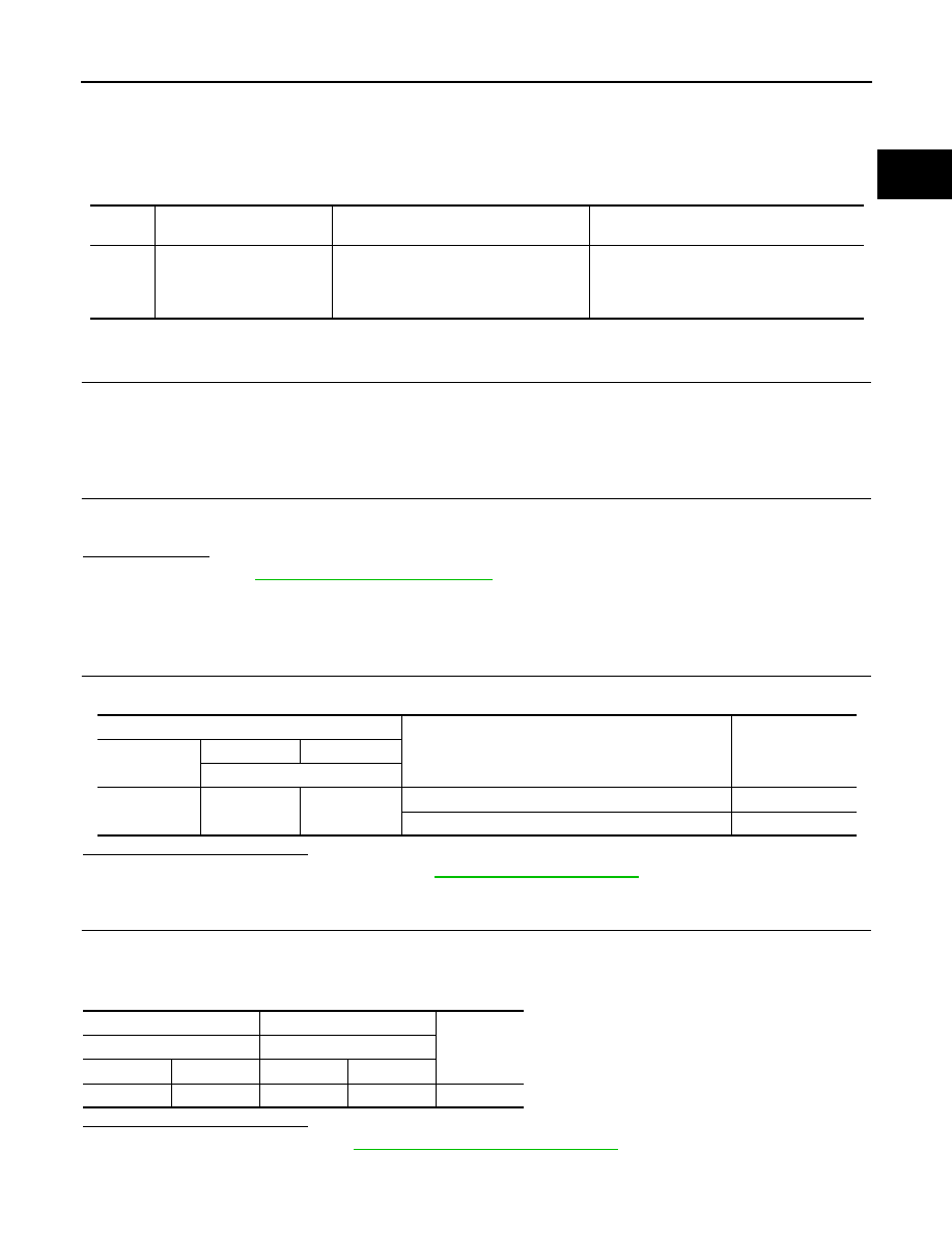
ECM
Condition
Voltage
Connector
+
–
Terminal
E59
13
29
Ignition switch: OFF
⇒
ON (fuel pump activated)
0 – 6.74 V
Ignition switch ON (fuel pump not activated)
0.05 V
+
−
Continuity
ECM
FPCM
Connector
Terminal
Connector
Terminal
E59
13
B77
9
Existed