Qashqai J11. Engine control system (K9K) - part 14


  Index      Nissan     Qashqai J11. Engine control system (K9K). Service and Repair Manual


Search            copyright infringement  


Content      ..     12      13      14      15     ..


Qashqai J11. Engine control system (K9K) - part 14


P0190 FRP SENSOR

ECK-209

< DTC/CIRCUIT DIAGNOSIS >

[K9K]

C

D

E

F

G

H

I

J

K

L

M

A

ECK

N

P

O

P0190 FRP SENSOR

DTC Logic

INFOID:0000000010289793

DTC DETECTION LOGIC

DTC CONFIRMATION PROCEDURE

1.

PERFORM DIAGNOSIS PROCEDURE

NOTE:
DTC P0190 can not duplicate.

>> Proceed to 

ECK-209, "Diagnosis Procedure"

.

Diagnosis Procedure

INFOID:0000000010289794

1.

CHECK ECM HARNESS CONNECTOR CONNECTIONS

1.

Turn ignition switch OFF.

2.

Check ECM harness connector connection F80.

Is the inspection result normal?

YES

>> GO TO 2.

NO

>> Repair or replace error-detected parts.

2.

CHECK FUEL RAIL PRESSURE SENSOR HARNESS CONNECTOR CONNECTIONS

Check fuel rail pressure sensor harness connector connection F40.

Is the inspection result normal?

YES

>> GO TO 3.

NO

>> Repair or replace error-detected parts.

3.

CHECK FUEL PIPING

Check fuel hoses and fuel tubes for clogging.

Is the inspection result normal?

YES

>> GO TO 4.

NO

>> Repair or replace error-detected parts.

4.

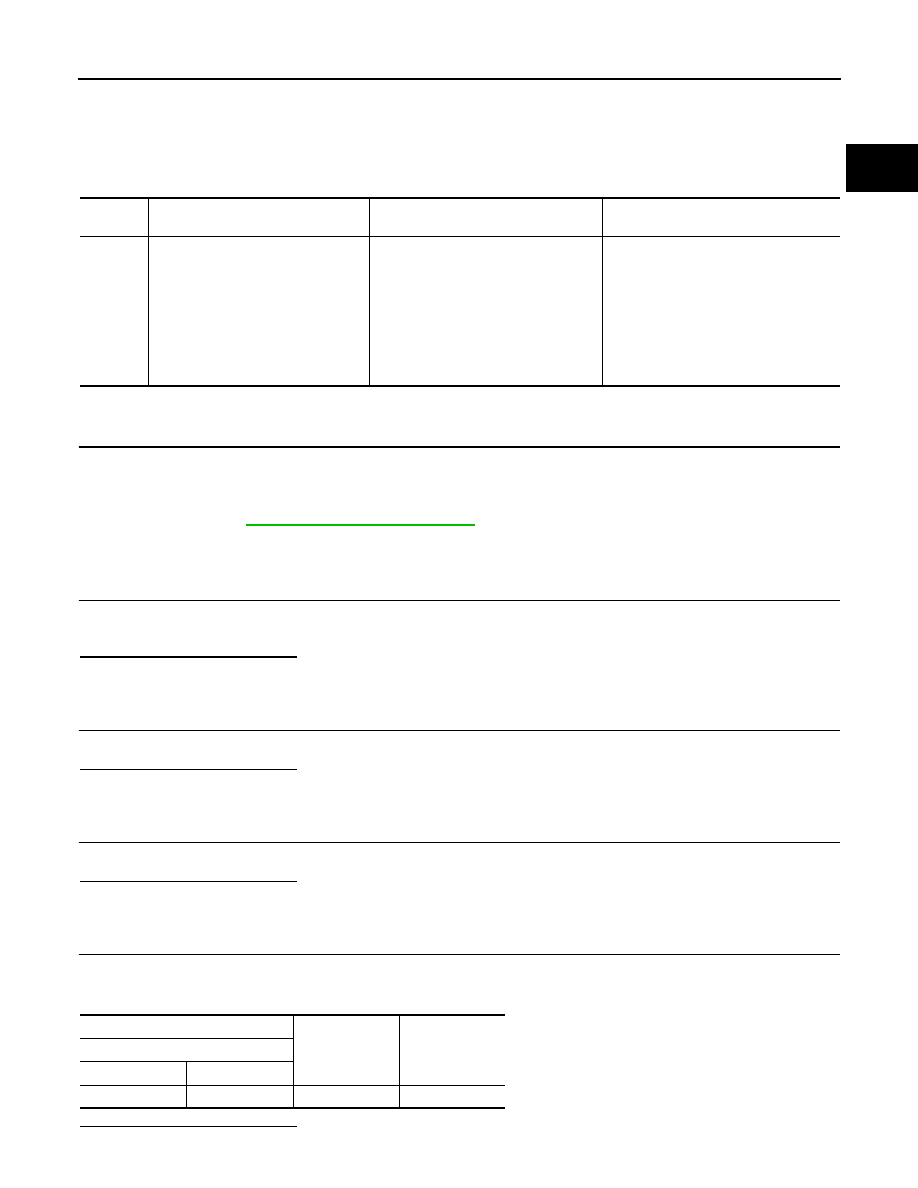
CHECK FUEL RAIL PRESSURE SENSOR POWER SUPPLY CIRCUIT

1.

Turn ignition switch ON.

2.

Check the power supply of the fuel rail pressure sensor.

Is the inspection result normal?

DTC No.

CONSULT screen terms

(Trouble diagnosis content)

DTC detecting condition

Possible cause

P0190

RAIL PRESSURE SENSOR CIR-
CUIT 
(Fuel rail pressure sensor “A” circuit)
• 1.DEF: VOLTAGE TOO LOW
• 2.DEF: VOLTAGE TOO HIGH
• 3.DEF: ABOVE THE MAX LEVEL
• 4.DEF: SIGNAL INCOHERENCE
• 5.DEF: INTERMITTENT SIGNAL 

INCOHERENCE

• An excessively low voltage from the 

sensor is sent to ECM.

• An excessively high voltage from the 

sensor is sent to ECM.

• An improper voltage signal from sen-

sor is sent to ECM.

• Harness or connectors

(Fuel rail pressure sensor circuit is 
open or shorted.)

• Fuel rail pressure sensor
• ECM

+

-

Voltage

(Approx.)

Fuel rail pressure sensor

Connector

Terminal

F40

3

Ground

5.0 V

ECK-210

< DTC/CIRCUIT DIAGNOSIS >

[K9K]

P0190 FRP SENSOR

YES

>> GO TO 5.

NO

>> Perform trouble diagnosis for power supply circuit.

5.

CHECK FUEL RAIL PRESSURE SENSOR CIRCUIT FOR OPEN AND SHORT

1.

Turn ignition switch OFF.

2.

Check fuel rail pressure sensor circuit for open and short.

Is the inspection result normal?

YES

>> Replace fuel rail pressure sensor.

NO

>> Repair or replace error-detected parts.

+

-

Continuity

ECM

Fuel rail pressure sensor

Connector

Terminal

Connector

Terminal

F80

45

F40

3

Existed

68

2

72

1

P0200 FUEL INJECTOR

ECK-211

< DTC/CIRCUIT DIAGNOSIS >

[K9K]

C

D

E

F

G

H

I

J

K

L

M

A

ECK

N

P

O

P0200 FUEL INJECTOR

DTC Logic

INFOID:0000000010289795

DTC DETECTION LOGIC

DTC CONFIRMATION PROCEDURE

1.

PRECONDITIONING

If DTC Confirmation Procedure has been previously conducted, always turn ignition switch OFF and wait at
least 1 minute before conducting the next test.

>> GO TO 2.

2.

PERFORM DTC CONFIRMATION PROCEDURE

1.

Start engine and let it idle for at least 1 second.

2.

Check DTC.

Is DTC detected?

YES

>>

ECK-211, "Diagnosis Procedure"

.

NO

>> INSPECTION END

Diagnosis Procedure

INFOID:0000000010289796

1.

CHECK FUEL RETURN HOSE

Check Fuel return hose.

Is the inspection result normal?

YES

>> GO TO 2.

NO

>> Repair or replace error-detected parts.

2.

CHECK FUEL INJECTOR CIRCUIT FOR OPEN AND SHORT

1.

Turn ignition switch OFF.

2.

Check fuel injector circuit for open and short.

Is the inspection result normal?

YES

>> GO TO 3.

DTC No.

CONSULT screen terms

(Trouble diagnosis content)

DTC detecting condition

Possible Cause

P0200

INJECTOR CONTROL 
CIRCUIT
(Injector circuit/open)
• 1.DEF: VALUES OUT-

SIDE TOLERANCES

• ECM detects fuel injectors circuit malfunction.
• Injector code is not stored into ECM.

• Harness or connectors
• Injector code error

Cylinder

+

-

Continuity

ECM

Fuel injector

Connector

Terminal

Connector

Terminal

No.1

F81

156

F155

1

Existed

160

2

No.2

153

F156

1

157

2

No.3

155

F157

1

159

2

No.4

154

F158

1

158

2

ECK-212

< DTC/CIRCUIT DIAGNOSIS >

[K9K]

P0200 FUEL INJECTOR

NO

>> Repair or replace error-detected parts.

3.

CHECK FUEL INJECTOR HARNESS CONNECTOR STATE

Check fuel injector harness connector state.

Is the inspection result normal?

YES

>> GO TO 4.

NO

>> Repair or replace error-detected parts.

4.

CHECK FUEL INJECTOR

Refer to 

ECK-212, "Component Inspection (Fuel Injector)"

.

Is the inspection result normal?

YES

>> Check intermittent incident. Refer to 

GI-41, "Intermittent Incident"

.

NO

>> Repair or replace error-detected parts.

Component Inspection (Fuel Injector)

INFOID:0000000010289797

1.

CHECK FUEL INJECTOR

1.

Turn ignition switch OFF.

2.

Disconnect fuel injector harness connector.

3.

Check the resistance between fuel injector terminals.

Is the inspection result normal?

YES

>> INSPECTION END

NO

>> Replace fuel injector. Refer to 

EM-293, "Removal and Installation"

.

Fuel injector

Condition

Resistance

+

Terminal

1

2

Temperature: 20

°

C (68

°

F)

150 – 250k

P0201, P0202, P0203, P0204 FUEL INJECTOR

ECK-213

< DTC/CIRCUIT DIAGNOSIS >

[K9K]

C

D

E

F

G

H

I

J

K

L

M

A

ECK

N

P

O

P0201, P0202, P0203, P0204 FUEL INJECTOR

DTC Logic

INFOID:0000000010434251

DTC DETECTION LOGIC

NOTE:
• If DTC P0201, P0202, P0203, or P0204 is displayed with DTC P0263, P0266, P0269, or P0272, perform

the trouble diagnosis for DTC P0263, P0266, P0269, or P0272. Refer to 

ECK-226, "DTC Logic"

.

DTC CONFIRMATION PROCEDURE

1.

PRECONDITIONING

If DTC Confirmation Procedure has been previously conducted, always turn ignition switch OFF and wait at
least 1 minute before conducting the next test.

>> GO TO 2.

2.

PERFORM DTC CONFIRMATION PROCEDURE

1.

Start engine and let it idle for at least 1 second.

2.

Check DTC.

Is DTC detected?

YES

>>

ECK-214, "Diagnosis Procedure"

.

NO

>> INSPECTION END

DTC No.

CONSULT screen terms

(Trouble diagnosis content)

DTC detecting condition

Possible cause

P0201

CYLINDER 1 INJECTOR CIRC
(Injector circuit/open - cylinder 1)
• 1.DEF: AT MAXIMUM LIMIT
• 2.DEF: SIGNAL INCOHERENCE
• 3.DEF: COMPARISON OF CONFORMITY IN-

FORMATION (CHECKSUM)

• 4.DEF: IMPROPER SIGNAL SHAPE
• CO: OPEN CIRCUIT

• ECM detects fuel injectors circuit 

are open.

• ECM error
• Injector code is not stored into 

ECM.

• An improper voltage signal from 

fuel injector is sent to ECM.

• ECM detects an improper fuel in-

jection time.

• ECM detects an improper fuel in-

jection mass.

• Harness or connectors

(The fuel injector circuit is 
open.)

• Fuel injector
• Injector code error
• ECM

P0202

CYLINDER 1 INJECTOR CIRC
(Injector circuit/open - cylinder 2)
• 1.DEF: AT MAXIMUM LIMIT
• 2.DEF: SIGNAL INCOHERENCE
• 3.DEF: COMPARISON OF CONFORMITY IN-

FORMATION (CHECKSUM)

• 4.DEF: IMPROPER SIGNAL SHAPE
• CO: OPEN CIRCUIT

P0203

CYLINDER 1 INJECTOR CIRC
(Injector circuit/open - cylinder 3)
• 1.DEF: AT MAXIMUM LIMIT
• 2.DEF: SIGNAL INCOHERENCE
• 3.DEF: COMPARISON OF CONFORMITY IN-

FORMATION (CHECKSUM)

• 4.DEF: IMPROPER SIGNAL SHAPE
• CO: OPEN CIRCUIT

P0204

CYLINDER 1 INJECTOR CIRC
(Injector circuit/open - cylinder 4)
NO. 4 cylinder fuel injector circuit
• 1.DEF: AT MAXIMUM LIMIT
• 2.DEF: SIGNAL INCOHERENCE
• 3.DEF: COMPARISON OF CONFORMITY IN-

FORMATION (CHECKSUM)

• 4.DEF: IMPROPER SIGNAL SHAPE
• CO: OPEN CIRCUIT

ECK-214

< DTC/CIRCUIT DIAGNOSIS >

[K9K]

P0201, P0202, P0203, P0204 FUEL INJECTOR

Diagnosis Procedure

INFOID:0000000010434252

1.

CHECK FUEL RETURN HOSE

Check Fuel return hose.

Is the inspection result normal?

YES

>> GO TO 2.

NO

>> Repair or replace error-detected parts.

2.

CHECK FUEL INJECTOR CIRCUIT FOR OPEN AND SHORT

1.

Turn ignition switch OFF.

2.

Check fuel injector circuit for open and short.

Is the inspection result normal?

YES

>> GO TO 3.

NO

>> Repair or replace error-detected parts.

3.

CHECK FUEL INJECTOR HARNESS CONNECTOR STATE

Check fuel injector harness connector state.

Is the inspection result normal?

YES

>> GO TO 4.

NO

>> Repair or replace error-detected parts.

4.

CHECK FUEL INJECTOR

Refer to 

ECK-214, "Component Inspection (Fuel Injector)"

.

Is the inspection result normal?

YES

>> Check intermittent incident. Refer to 

GI-41, "Intermittent Incident"

.

NO

>> Repair or replace error-detected parts.

Component Inspection (Fuel Injector)

INFOID:0000000010434253

1.

CHECK FUEL INJECTOR

1.

Turn ignition switch OFF.

2.

Disconnect fuel injector harness connector.

3.

Check the resistance between fuel injector terminals.

Is the inspection result normal?

YES

>> INSPECTION END

Cylinder

+

-

Continuity

ECM

Fuel injector

Connector

Terminal

Connector

Terminal

No.1

F81

156

F155

1

Existed

160

2

No.2

153

F156

1

157

2

No.3

155

F157

1

159

2

No.4

154

F158

1

158

2

Fuel injector

Condition

Resistance

+

Terminal

1

2

Temperature: 20

°

C (68

°

F)

150 – 250k

P0201, P0202, P0203, P0204 FUEL INJECTOR

ECK-215

< DTC/CIRCUIT DIAGNOSIS >

[K9K]

C

D

E

F

G

H

I

J

K

L

M

A

ECK

N

P

O

NO

>> Replace fuel injector. Refer to 

EM-293, "Removal and Installation"

.

ECK-216

< DTC/CIRCUIT DIAGNOSIS >

[K9K]

P0217 ENGINE OVER TEMPERATURE

P0217 ENGINE OVER TEMPERATURE

DTC Logic

INFOID:0000000010289798

DTC DETECTION LOGIC

If the cooling fan or other component in the cooling system malfunctions, engine coolant temperature will rise.
When the engine coolant temperature reaches an abnormally high temperature condition, a malfunction is
indicated.
NOTE:
• If DTC P0217 is displayed with DTC P0115, perform the trouble diagnosis for DTC P0115. Refer to

ECK-201, "DTC Logic"

.

CAUTION:

When a malfunction is indicated, be sure to replace the coolant. Also, replace the engine oil. 
1.

Fill radiator with coolant up to specified level with a filling speed of 2 liters per minute. Be sure to
use coolant with the proper mixture ratio.

2.

After refilling coolant, run engine to ensure that no water-flow noise is emitted.

DTC CONFIRMATION PROCEDURE

1.

PERFORM COMPONENT FUNCTION CHECK

Perform component function check. Refer to 

ECK-216, "Component Function Check"

.

NOTE:
Use component function check to check the overall function of the cooling fan. During this check, a DTC might
not be confirmed.
Is the inspection result normal?

YES

>> INSPECTION END

NO

>> Go to 

ECK-217, "Diagnosis Procedure"

.

Component Function Check

INFOID:0000000010289799

1.

PERFORM COMPONENT FUNCTION CHECK-1

WARNING:

Never remove the reservoir tank cap when the engine is hot. Serious burns could be caused by high
pressure fluid escaping from the radiator.
Wrap a thick cloth around cap. Carefully remove the cap by turning it a quarter turn to allow built-up
pressure to escape. Then turn the cap all the way off.
Check the coolant level in the reservoir tank and radiator.
Allow engine to cool before checking coolant level.

Is the coolant level in the reservoir tank and/or radiator below the
proper range?

YES

>> Proceed to 

ECK-217, "Diagnosis Procedure"

.

NO

>> GO TO 2.

DTC No.

CONSULT screen terms

(Trouble diagnosis content)

DTC detecting condition

Possible cause

P0217

ENGINE OVERHEATING
(Engine coolant over tempera-
ture condition)
• 1.DEF: OPERATION TEM-

PERATURE TOO HIGH

When engine coolant temperature is 110

°

C or more for 2 

seconds.

• Cooling fan
• Radiator hose
• Radiator
• Radiator  cap
• Water pump
• Thermostat
• Engine coolant temper-

ature sensor

• ECM

SEF621W

P0217 ENGINE OVER TEMPERATURE

ECK-217

< DTC/CIRCUIT DIAGNOSIS >

[K9K]

C

D

E

F

G

H

I

J

K

L

M

A

ECK

N

P

O

2.

PERFORM COMPONENT FUNCTION CHECK-2

Confirm whether customer filled the coolant or not.
Did customer fill the coolant?

YES

>> Proceed to 

ECK-217, "Diagnosis Procedure"

.

NO

>> GO TO 3.

3.

PERFORM COMPONENT FUNCTION CHECK-3

1.

Start engine and let it idle.

2.

Turn air conditioner switch and blower fan switch ON.

3.

Make sure that cooling fan operates at low speed.

Is the inspection result normal?

YES

>> GO TO 4.

NO

>> Proceed to 

ECK-217, "Diagnosis Procedure"

.

4.

PERFORM COMPONENT FUNCTION CHECK-4

1.

Turn ignition switch OFF.

2.

Turn air conditioner switch and blower fan switch OFF.

3.

Disconnect engine coolant temperature sensor harness connector.

4.

Connect 150

 resistor to engine coolant temperature sensor harness connector.

5.

Restart engine and make sure that cooling fan operates at higher speed than low speed.

Is the inspection result normal?

YES

>> INSPECTION END

NO

>> Proceed to 

ECK-217, "Diagnosis Procedure"

.

Diagnosis Procedure

INFOID:0000000010289800

1.

CHECK COOLING FAN OPERATION

Check cooling fan operation.

Is the inspection result normal?

YES

>> GO TO 2.

NO

>> Repair or replace malfunctioning part.

2.

CHECK COOLING SYSTEM FOR LEAK-1

Check cooling system for leak.
Is leakage detected?

YES

>> GO TO 3.

NO

>> GO TO 4.

3.

CHECK COOLING SYSTEM FOR LEAK-2

Check the following for leak.
• Hose
• Radiator
• Radiator cap
• Water pump
• Reservoir tank

>> Repair or replace malfunctioning part.

4.

CHECK RADIATOR CAP

Check radiator cap.

Is the inspection result normal?

YES

>> GO TO 5.

NO

>> Replace radiator cap.

5.

CHECK THERMOSTAT

Check thermostat.

ECK-218

< DTC/CIRCUIT DIAGNOSIS >

[K9K]

P0217 ENGINE OVER TEMPERATURE

Is the inspection result normal?

YES

>> GO TO 6.

NO

>> Replace thermostat.

6.

CHECK ENGINE COOLANT TEMPERATURE SENSOR

Check engine coolant temperature sensor. Refer to 

ECK-202, "Component Inspection (Engine Coolant Tem-

perature Sensor)"

.

Is the inspection result normal?

YES

>> Perform overheating cause analysis. Refer to 

CO-63, "Troubleshooting Chart"

.

NO

>> Replace engine coolant temperature sensor.

P0225 APP SENSOR

ECK-219

< DTC/CIRCUIT DIAGNOSIS >

[K9K]

C

D

E

F

G

H

I

J

K

L

M

A

ECK

N

P

O

P0225 APP SENSOR

DTC Logic

INFOID:0000000010289801

DTC DETECTION LOGIC

NOTE:
If DTC P0225 is displayed with DTC P0641, first perform the trouble diagnosis for DTC P0641. Refer to

ECK-277, "DTC Logic"

.

DTC CONFIRMATION PROCEDURE

1.

PRECONDITIONING

If DTC Confirmation Procedure has been previously conducted, always turn ignition switch OFF and wait at
least 1 minute before conducting the next test.

>> GO TO 2.

2.

PERFORM DTC CONFIRMATION PROCEDURE

1.

Turn ignition switch ON and wait at least 1 second.

2.

Check DTC.

Is DTC detected?

YES

>> Proceed to 

ECK-219, "Diagnosis Procedure"

.

NO

>> INSPECTION END

Diagnosis Procedure

INFOID:0000000010289802

1.

CHECK ACCELERATOR PEDAL POSITION SENSOR 1 POWER SUPPLY CIRCUIT

Check the power supply of the accelerator pedal position sensor 1.

Is the inspection result normal?

YES

>> GO TO 2.

NO

>> Perform trouble diagnosis for power supply circuit.

2.

CHECK ACCELERATOR PEDAL POSITION SENSOR 1 CIRCUIT FOR OPEN AND SHORT

1.

Turn ignition switch OFF.

2.

Check accelerator pedal position sensor 1 circuit for open and short.

DTC No.

CONSULT screen terms

(Trouble diagnosis content)

DTC detecting condition

Possible cause

P0225

PEDAL POTENTIOMETER CIR-
CUIT TRACK 1
(Throttle/pedal position sensor/
switch “C” circuit)
• 1.DEF: VOLTAGE TOO HIGH
• 2.DEF: VOLTAGE TOO LOW 

• An excessively low voltage from the sen-

sor is sent to ECM.

• An excessively high voltage from the sen-

sor is sent to ECM.

• Harness or connectors

(Accelerator pedal position sensor 
circuit is open or shorted.)

• Accelerator pedal position sensor

(APP sensor 1)

• ECM

+

-

Voltage

(Approx.)

APP sensor

Connector

Terminal

E20

4

Ground

5.0 V

ECK-220

< DTC/CIRCUIT DIAGNOSIS >

[K9K]

P0225 APP SENSOR

Is the inspection result normal?

YES

>> GO TO 3.

NO

>> Repair or replace error-detected parts.

3.

CHECK ACCELERATOR PEDAL POSITION SENSOR 

Refer to 

ECK-220, "Component Inspection (Accelerator Pedal Position Sensor)"

.

Is the inspection result normal?

YES

>> Check intermittent incident. Refer to 

GI-41, "Intermittent Incident"

.

NO

>> Replace error-detected parts.

Component Inspection (Accelerator Pedal Position Sensor)

INFOID:0000000010289803

1.

CHECK ACCELERATOR PEDAL POSITION SENSOR

1.

Reconnect all harness connectors disconnected.

2.

Turn ignition switch ON.

3.

Check the voltage between ECM harness connector terminals as follows.

Is the inspection result normal?

YES

>> INSPECTION END

NO

>> Replace accelerator pedal assembly.

+

-

Continuity

ECM

APP sensor

Connector

Terminal

Connector

Terminal

E59

27

E20

4

Existed

30

2

31

3

ECM

Condition

Voltage

Connector

+

-

Terminal

E59

31

30

Accelerator pedal

Fully released

0.6 - 0.9 V

Fully depressed

3.9 - 4.7 V

22

21

Fully released

0.3 - 0.6 V

Fully depressed

1.95 - 2.4 V

P0226 APP SENSOR

ECK-221

< DTC/CIRCUIT DIAGNOSIS >

[K9K]

C

D

E

F

G

H

I

J

K

L

M

A

ECK

N

P

O

P0226 APP SENSOR

DTC Logic

INFOID:0000000010289804

DTC DETECTION LOGIC

DTC CONFIRMATION PROCEDURE

1.

PRECONDITIONING

If DTC Confirmation Procedure has been previously conducted, always turn ignition switch OFF and wait at
least 1 minute before conducting the next test.

>> GO TO 2.

2.

PERFORM DTC CONFIRMATION PROCEDURE

1.

Turn ignition switch ON and wait at least 1 second.

2.

Check DTC.

Is DTC detected?

YES

>> Proceed to 

ECK-221, "Diagnosis Procedure"

.

NO

>> INSPECTION END

Diagnosis Procedure

INFOID:0000000010289805

1.

CHECK ACCELERATOR PEDAL STATE

Check that the accelerator pedal is not stuck with the driver side floor mat.

Is the inspection result normal?

YES

>> GO TO 2.

NO

>> Repair malfunction.

2.

CHECK STOP LAMP SWITCH

Refer to 

ECK-254, "Component Inspection (Brake Pedal Position Switch)"

.

Is the inspection result normal?

YES

>> GO TO 3.

NO

>> Replace error-detected parts.

3.

CHECK ACCELERATOR PEDAL POSITION SENSOR POWER SUPPLY CIRCUIT

Check the power supply of the accelerator pedal position sensor.

DTC No.

CONSULT screen terms

(Trouble diagnosis content)

DTC detection condition

Possible cause

P0226

BRAKE/ACCELERATOR PEDAL 
POSITIONS
(Throttle/pedal position sensor/
switch “C” circuit range/perfor-
mance)
• 1.DEF: JAMMED ACCELERA-

TOR PEDAL DETECTED

• 2.DEF: JAMMED ACCELERA-

TOR PEDAL DETECTED

• 3.DEF: IMPLAUSIBLE SIGNAL
• 4.DEF: FAULT ON GANGS 1 

AND 2 OF THE PEDAL PO-
TENTIOMETER

• ECM does not receive a signal sent from 

APP sensor 1 and 2.

• ECM detects a invalid signal sent from 

APP sensor 1 and 2.

• Harness or connectors

(APP sensor 1 and 2 circuit is open 
or shorted.)

• Accelerator pedal position sensor

ECK-222

< DTC/CIRCUIT DIAGNOSIS >

[K9K]

P0226 APP SENSOR

Is the inspection result normal?

YES

>> GO TO 4.

NO

>> Perform trouble diagnosis for power supply circuit.

4.

CHECK ACCELERATOR PEDAL POSITION SENSOR CIRCUIT FOR OPEN AND SHORT

1.

Turn ignition switch OFF.

2.

Check accelerator pedal position sensor circuit for open and short.

Is the inspection result normal?

YES

>> GO TO 5.

NO

>> Repair or replace error-detected parts.

5.

CHECK ACCELERATOR PEDAL POSITION SENSOR 

Refer to 

ECK-222, "Component Inspection (Accelerator Pedal Position Sensor)"

.

Is the inspection result normal?

YES

>> Check intermittent incident. Refer to 

GI-41, "Intermittent Incident"

.

NO

>> Replace error-detected parts.

Component Inspection (Accelerator Pedal Position Sensor)

INFOID:0000000010289806

1.

CHECK ACCELERATOR PEDAL POSITION SENSOR

1.

Reconnect all harness connectors disconnected.

2.

Turn ignition switch ON.

3.

Check the voltage between ECM harness connector terminals as follows.

Is the inspection result normal?

YES

>> INSPECTION END

NO

>> Replace accelerator pedal assembly.

+

-

Voltage

(Approx.)

APP sensor

Connector

Terminal

E20

4

Ground

5.0 V

5

Sensor

+

-

Continuity

ECM

APP sensor

Connector

Terminal

Connector

Terminal

1

E59

27

E20

4

Existed

30

2

31

3

2

21

1

22

6

23

5

ECM

Condition

Voltage

Connector

+

-

Terminal

E59

31

30

Accelerator pedal

Fully released

0.6 - 0.9 V

Fully depressed

3.9 - 4.7 V

22

21

Fully released

0.3 - 0.6 V

Fully depressed

1.95 - 2.4 V

P025A FUEL PUMP

ECK-223

< DTC/CIRCUIT DIAGNOSIS >

[K9K]

C

D

E

F

G

H

I

J

K

L

M

A

ECK

N

P

O

P025A FUEL PUMP

DTC Logic

INFOID:0000000010289807

DTC DETECTION LOGIC

NOTE:
If DTC P025A is displayed with IPDM E/R DTC, perform the trouble diagnosis for IPDM E/R DTC. Refer
to 

PCS-37, "DTC Index"

.

DTC CONFIRMATION PROCEDURE

1.

PRECONDITIONING

If DTC Confirmation Procedure has been previously conducted, always turn ignition switch OFF and wait at
least 1 minute before conducting the next test.

>> GO TO 2.

2.

PERFORM DTC CONFIRMATION PROCEDURE

1.

Turn ignition switch ON and wait at least 1 second.

2.

Check DTC.

Is DTC detected?

YES

>> Proceed to 

ECK-223, "Diagnosis Procedure"

.

NO

>> INSPECTION END

Diagnosis Procedure

INFOID:0000000010289808

1.

CHECK GROUND CONNECTION

1.

Turn ignition switch OFF.

2.

Check ground connection E5. Refer to Ground Inspection in 

GI-43, "Circuit Inspection"

.

Is the inspection result normal?

YES

>> GO TO 2.

NO

>> Repair or replace ground connection.

2.

CHECK FUEL PUMP RELAY CIRCUIT-I

Check the voltage between ECM harness connector and ground.

Is the inspection result normal?

YES

>> GO TO 5.

NO

>> GO TO 3.

3.

CHECK FUEL PUMP RELAY CIRCUIT-II

1.

Disconnect ECM harness connector.

2.

Disconnect IPDM E/R harness connector.

3.

Check the continuity between ECM harness connector and IPDM E/R harness connector.

DTC

CONSULT screen terms

(Trouble diagnosis content)

DTC detecting condition

Possible cause

P025A

FUEL PUMP MODULE A
(Fuel pump module control 
circuit/open)

• Fuel pump relay circuit is open
• Fuel pump relay circuit is short to ground 

or power

• Harness or connectors

(Fuel pump relay circuit is open or shorted.)

• Fuel  pump  relay
• ECM

ECM

Voltage

+

Connector

Terminal

Connector

Terminal

F80

89

E59

25

Battery voltage

ECK-224

< DTC/CIRCUIT DIAGNOSIS >

[K9K]

P025A FUEL PUMP

4.

Also check harness for short to ground and short to power.

Is the inspection result normal?

YES

>> GO TO 4.

NO

>> Repair or replace error-detected parts.

4.

CHECK 20A FUSE

1.

Disconnect 20A fuse (No. 61) from IPDM E/R.

2.

Check 20A fuse.

Is the inspection result normal?

YES

>> GO TO 5.

NO

>> Replace 20A fuse.

5.

CHECK INTERMITTENT INCIDENT

Refer to 

GI-41, "Intermittent Incident"

.

>> INSPECTION END

ECM

IPDM E/R

Continuity

Connector

Terminal

Connector

Terminal

F80

89

F90

106

Existed


Content      ..     12      13      14      15     ..