Qashqai J11. Engine control system (K9K) - part 12
 

  Index      Nissan     Qashqai J11. Engine control system (K9K). Service and Repair Manual


Search            copyright infringement  


Content      ..     10      11      12      13     ..


Qashqai J11. Engine control system (K9K) - part 12


P0001 FUEL PUMP

ECK-177

< DTC/CIRCUIT DIAGNOSIS >

[K9K]

C

D

E

F

G

H

I

J

K

L

M

A

ECK

N

P

O

P0001 FUEL PUMP

DTC Logic

INFOID:0000000010289742

DTC DETECTION LOGIC

NOTE:
If DTC P0001 is displayed with DTC P0560 or P0657, first perform trouble diagnosis for DTC P0560 or
P0657. Refer to 

ECK-261, "DTC Logic"

 (DTC P0560) or 

ECK-282, "DTC Logic"

 (DTC P0657).

DTC CONFIRMATION PROCEDURE

1.

PRECONDITIONING

If DTC Confirmation Procedure has been previously conducted, always turn ignition switch OFF and wait at
least 1 minute before conducting the next test.

>> GO TO 2.

2.

PERFORM DTC CONFIRMATION PROCEDURE

1.

Turn ignition switch ON and wait at least 2 seconds.

2.

Check DTC.

Is DTC detected?

YES

>> Proceed to 

ECK-177, "Diagnosis Procedure"

.

NO

>> INSPECTION END

Diagnosis Procedure

INFOID:0000000010289743

1.

CHECK HIGH PRESSURE FUEL PUMP POWER SUPPLY CIRCUIT

1.

Turn ignition switch OFF.

2.

Disconnect high pressure fuel pump harness connector.

3.

Turn ignition switch ON.

4.

Check the voltage between high pressure fuel pump harness connector and ground.

Is the inspection result normal?

YES

>> GO TO 2.

NO

>> Perform the trouble diagnosis for power supply circuit.

2.

CHECK HIGH PRESSURE FUEL PUMP GROUND CIRCUIT FOR OPEN AND SHORT

1.

Turn ignition switch OFF.

2.

Disconnect ECM harness connector.

3.

Check the continuity between high pressure fuel pump harness connector and ECM harness connector.

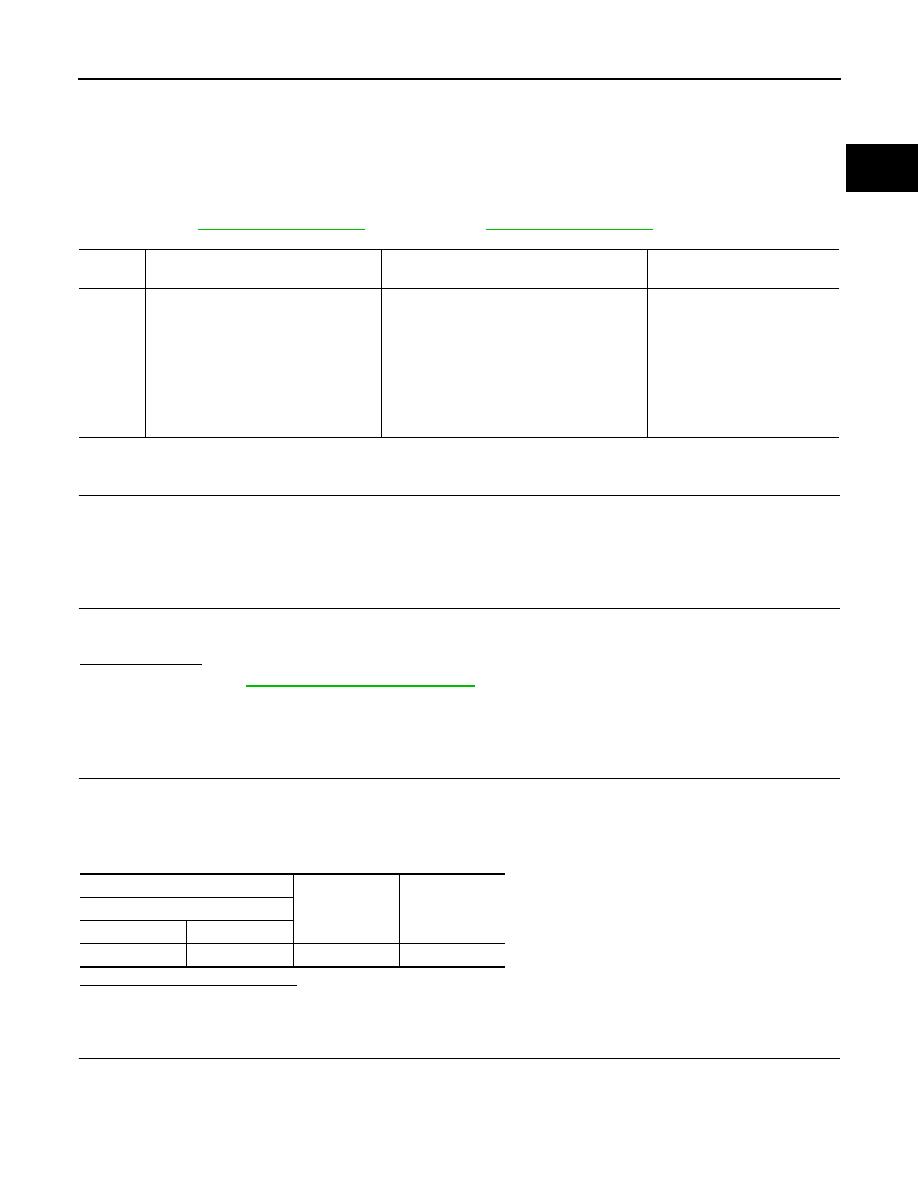
DTC No.

CONSULT screen terms

(Trouble diagnosis content)

DTC detecting condition

Possible cause

P0001

FUEL FLOW REGULATOR CIRCUIT
(Fuel volume regulator control circuit/
open)
• 1.DEF: INLET FLAP BLOCKED 

CLOSED

• 2.DEF: INLET FLAP BLOCKED 

OPEN

• 3.DEF: CIRCUIT CURRENT ABOVE 

THRESHOLD

• ECM detects a short circuit to ground.
• ECM detects a short circuit to battery.
• ECM detects a open circuit.

• Harness or connectors

(High pressure fuel pump cir-
cuit is open or shorted.)

• High pressure fuel pump

+

-

Voltage

High pressure fuel pump

Connector

Terminal

F133

1

Ground

Battery voltage

ECK-178

< DTC/CIRCUIT DIAGNOSIS >

[K9K]

P0001 FUEL PUMP

4.

Also check harness for short to ground and short to power. 

Is the inspection result normal?

YES

>> GO TO 3.

NO

>> Repair or replace error-detected parts.

3.

CHECK HIGH PRESSURE FUEL PUMP

Refer to 

ECK-178, "Component Inspection (High Pressure Fuel Pump)"

.

Is the inspection result normal?

YES

>> Check intermittent incident. Refer to 

GI-41, "Intermittent Incident"

.

NO

>> Replace error-detected parts.

Component Inspection (High Pressure Fuel Pump)

INFOID:0000000010289744

1.

CHECK HIGH PRESSURE FUEL PUMP

1.

Disconnect high pressure fuel pump harness connector.

2.

Check the resistance between high pressure fuel pump terminals as follows.

Is the inspection result normal?

YES

>> INSPECTION END

NO

>> Replace high pressure fuel pump.

+

-

Continuity

High pressure fuel pump

ECM

Connector

Terminal

Connector

Terminal

F133

2

F80

92

Existed

High pressure fuel pump

Condition

Resistance

+

-

Terminal

1

2

Temperature 

°

C (

°

F)

20 (68)

2.55 - 2.81 

P0002 FUEL PRESSURE

ECK-179

< DTC/CIRCUIT DIAGNOSIS >

[K9K]

C

D

E

F

G

H

I

J

K

L

M

A

ECK

N

P

O

P0002 FUEL PRESSURE

DTC Logic

INFOID:0000000010289745

DTC DETECTION LOGIC

NOTE:
If DTC P0002 is displayed with DTC P0001, P0087, P0089, P0201, P0115, P0180, P0200, P0202, P0203,
P0204 or P0627, first perform trouble diagnosis for DTC P0001, P0087, P0089, P0201, P0115, P0180,
P0200, P0202, P0203, P0204 or P0627. Refer to 

ECK-97, "DTC Index"

.

DTC CONFIRMATION PROCEDURE

1.

PERFORM DIAGNOSIS PROCEDURE

NOTE:
DTC P0002 can not duplicate.

>> Proceed to 

ECK-179, "Diagnosis Procedure"

.

Diagnosis Procedure

INFOID:0000000010289746

1.

CHECK FUEL LEVEL

Check that the fuel level is enough.
Is the inspection result normal?

YES

>> GO TO 2.

NO

>> Refuel.

2.

PERFORM FUEL FILTER AIR BLEEDING

NOTE:
If the DTC is detected because of air mixed with fuel (i.e.: caused by lack of fuel), it may become nor-
mal by performing following procedure.
1.

Turn ignition switch ON.

2.

Perform fuel filter air bleeding. Refer to 

FL-34, "Air Bleeding"

.

3.

Erase DTC.

4.

Perform DTC confirmation procedure again. Refer to 

ECK-179, "DTC Logic"

.

Is the DTC P0002 detected again?

YES

>> GO TO 3.

NO

>> INSPECTION END

3.

CHECK FUEL FILTER

Check the correctness of the fuel filter.

Is the inspection result normal?

YES

>> GO TO 4.

NO

>> Replace error-detected parts.

DTC No.

CONSULT screen terms

(Trouble diagnosis content)

DTC detecting condition

Possible cause

P0002

FLOW CONTROL ADAPTIVE
(Fuel volume regulator control circuit 
range/performance)
• 1.DEF: PARAMETER AT MAXIMUM 

STOP

• 2.DEF: PARAMETER AT MINIMUM 

STOP

• 3.DEF: ABOVE THE MAX LEVEL
• 4.DEF: CLOGGED.
• 5.DEF: OFFSET IMPLAUSIBLE
• 6.DEF: IMPLAUSIBLE SIGNAL
• 7.DEF: SIGNAL STUCK LOW

• Fuel rail pressure is excessively high.
• Fuel rail pressure is excessively low.
• Fuel pressure of low pressure fuel circuit is 

excessively high.

• High pressure fuel pump
• Fuel leakage
• Fuel filter clogged
• Injectors clogged
• Fuel leakage on fuel rail pres-

sure limiter

• High pressure fuel pump 

blocked

ECK-180

< DTC/CIRCUIT DIAGNOSIS >

[K9K]

P0002 FUEL PRESSURE

4.

CHECK FOR FUEL LEAK

Check for fuel leakage at fuel circuit.
Is the inspection result normal?

YES

>> GO TO 5.

NO

>> Repair or replace malfunctioning parts.

5.

CHECK HIGH PRESSURE FUEL PUMP

Check high pressure fuel pump. Refer to 

ECK-180, "Component Inspection (High Pressure Fuel Pump)"

.

Is the inspection result normal?

YES

>> GO TO 6.

NO

>> Replace error-detected parts.

6.

CHECK FUEL INJECTOR

Check fuel injector. Refer to 

ECK-180, "Component Inspection (Fuel Injector)"

.

Is the inspection result normal?

YES

>> GO TO 7.

NO

>> Replace error-detected parts.

7.

CHECK FUEL RAIL PRESSURE LIMITER

Check fuel rail pressure limiter.
Is the inspection result normal?

YES

>> Check intermittent incident. Refer to 

GI-41, "Intermittent Incident"

.

NO

>> Replace error-detected parts.

Component Inspection (High Pressure Fuel Pump)

INFOID:0000000010289747

1.

CHECK HIGH PRESSURE FUEL PUMP

1.

Disconnect high pressure fuel pump harness connector.

2.

Check the resistance between high pressure fuel pump terminals as follows.

Is the inspection result normal?

YES

>> INSPECTION END

NO

>> Replace high pressure fuel pump.

Component Inspection (Fuel Injector)

INFOID:0000000010289748

1.

CHECK FUEL INJECTOR

1.

Turn ignition switch OFF.

2.

Disconnect fuel injector harness connector.

3.

Check the resistance between fuel injector terminals.

Is the inspection result normal?

YES

>> INSPECTION END

NO

>> Replace fuel injector.

High pressure fuel pump

Condition

Resistance

+

-

Terminal

1

2

Temperature 

°

C (

°

F)

20 (68)

2.55 - 2.81 

Fuel injector

Condition

Resistance

+

Terminal

1

2

Temperature: 20

°

C (68

°

F)

150 – 250k 

P0016 CKP - CMP CORRELATION

ECK-181

< DTC/CIRCUIT DIAGNOSIS >

[K9K]

C

D

E

F

G

H

I

J

K

L

M

A

ECK

N

P

O

P0016 CKP - CMP CORRELATION

DTC Logic

INFOID:0000000010289749

DTC DETECTION LOGIC

NOTE:
• If DTC P0016 is displayed with DTC P0335, P0560, P0657, or P0641, perform the trouble diagnosis for

DTC P0335, P0560, P0657, or P0641. Refer to 

ECK-97, "DTC Index"

.

DTC CONFIRMATION PROCEDURE

1.

PRECONDITIONING

If DTC Confirmation Procedure has been previously conducted, always turn ignition switch OFF and wait at
least 1 minute before conducting the next test.

>> GO TO 2.

2.

PERFORM DTC CONFIRMATION PROCEDURE

1.

Start engine and let it idle for at least 1 second.

2.

Check DTC.

Is DTC detected?

YES

>>

ECK-181, "Diagnosis Procedure"

.

NO

>> INSPECTION END

Diagnosis Procedure

INFOID:0000000010289750

1.

CHECK CKP SENSOR

Check CKP sensor. Refer to 

ECK-182, "Component Inspection (Crankshaft Position Sensor)"

.

Is the inspection result normal?

YES

>> GO TO 2.

NO

>> Replace error-detected parts.

2.

CHECK CMP SENSOR 

Check CMP sensor. Refer to 

ECK-182, "Component Inspection (Camshaft Position Sensor)"

.

Is the inspection result normal?

YES

>> GO TO 3.

NO

>> Replace error-detected parts.

3.

CHECK SIGNAL PLATE OF CAMSHAFT REAR END

Visually check for chipping signal plate of camshaft rear end.

Is the inspection result normal?

YES

>> GO TO 4.

NO

>> Repair or replace camshaft RH.

4.

CHECK SIGNAL PLATE WITH FLYWHEEL

Visually check for chipping signal plate with flywheel.

DTC No.

CONSULT screen terms

(Trouble diagnosis content)

DTC detecting condition

Possible cause

P0016

COHER BTWN CSFT SEN/
ENG SPD
(Crankshaft position - cam-
shaft position correlation bank 
1 sensor A)

• 1.DEF: SIGNAL INCOHER-

ENCE

The correlation between crankshaft position 
sensor signal and camshaft position sensor 
signal is out of the normal range.

• Harness or connectors

(CKP sensor circuit is open or shorted.)
(CMP sensor circuit is open or shorted.)

• Crankshaft position sensor
• Camshaft position sensor
• Timing chain
• Signal plate

ECK-182

< DTC/CIRCUIT DIAGNOSIS >

[K9K]

P0016 CKP - CMP CORRELATION

Is the inspection result normal?

YES

>> GO TO 5.

NO

>> Replace signal plate with flywheel.

5.

CHECK TIMING BELT

Check timing belt.
Is the inspection result normal?

YES

>> Check intermittent incident. Refer to 

GI-41, "Intermittent Incident"

.

NO

>> Replace timing belt.

Component Inspection (Crankshaft Position Sensor)

INFOID:0000000010289751

1.

CHECK CRANKSHAFT POSITION SENSOR

1.

Turn ignition switch OFF.

2.

Disconnect crankshaft position (CKP) sensor harness connector.

3.

Check the resistance between CKP sensor terminals.

Is the inspection result normal?

YES

>> INSPECTION END

NO

>> Replace CKP sensor.

Component Inspection (Camshaft Position Sensor)

INFOID:0000000010289752

1.

CHECK CAMSHAFT POSITION SENSOR

1.

Turn ignition switch OFF.

2.

Disconnect camshaft position (CMP) sensor harness connector.

3.

Check the resistance between CMP sensor terminals.

Is the inspection result normal?

YES

>> INSPECTION END

NO

>> Replace CMP sensor.

CKP sensor

Condition

Resistance

+

Terminal

1

2

Temperature 

°

C (

°

F)

20 (68)

690 

CMP sensor

Resistance

+

Terminal

2

3

More than 100 k

P0045 TC BOOST CONTROL SOLENOID VALVE

ECK-183

< DTC/CIRCUIT DIAGNOSIS >

[K9K]

C

D

E

F

G

H

I

J

K

L

M

A

ECK

N

P

O

P0045 TC BOOST CONTROL SOLENOID VALVE

DTC Logic

INFOID:0000000010289753

DTC DETECTION LOGIC

DTC CONFIRMATION PROCEDURE

1.

PRECONDITIONING

If DTC Confirmation Procedure has been previously conducted, always turn ignition switch OFF and wait at
least 1 minute before conducting the next test.

>> GO TO 2.

2.

PERFORM DTC CONFIRMATION PROCEDURE

1.

Turn ignition switch ON and wait at least 1 second.

2.

Check DTC.

Is DTC detected?

YES

>> Proceed to 

ECK-183, "Diagnosis Procedure"

.

NO

>> INSPECTION END

Diagnosis Procedure

INFOID:0000000010289754

1.

CHECK ECM HARNESS CONNECTOR CONNECTION

1.

Turn ignition switch OFF. 

2.

Check ECM harness connector connection.

Is the inspection result normal?

YES

>> GO TO 2.

NO

>> Repair or replace ECM harness connector connection.

2.

CHECK TURBOCHARGER BOOST CONTROL SOLENOID VALVE HARNESS CONNECTOR CONNEC-

TION

Check turbocharger boost control solenoid valve harness connector connection.
Is the inspection result normal?

YES

>> GO TO 3.

NO

>> Repair or replace turbocharger boost control solenoid valve harness connector connection. Refer

to 

ECK-12, "Component Parts Location"

.

3.

CHECK TURBOCHARGER BOOST CONTROL SOLENOID VALVE POWER SUPPLY

1.

Turn ignition switch OFF.

2.

Disconnect turbocharger boost control solenoid valve harness connector.

3.

Turn ignition switch ON.

4.

Check the voltage between turbocharger boost control solenoid valve harness connector and ground.

DTC No.

CONSULT screen terms

(Trouble diagnosis content)

DTC detecting condition

Possible cause

P0045

TC SOLENOID VALVE CNTRL 
CIRC
(Turbocharger/supercharger boost 
control “A” circuit/open)
• 1.DEF: VOLTAGE TOO LOW
• 2.DEF: VOLTAGE TOO HIGH

• ECM detects turbocharger boost control 

solenoid valve circuit is open.

• ECM detects turbocharger boost control 

solenoid valve circuit is short to ground.

• ECM detects turbocharger boost control 

solenoid valve circuit is short to power.

• Harness or connectors

(Turbocharger boost control sole-
noid valve circuit is open or shorted.)

• Turbocharger boost control solenoid 

valve

ECK-184

< DTC/CIRCUIT DIAGNOSIS >

[K9K]

P0045 TC BOOST CONTROL SOLENOID VALVE

Is the inspection result normal?

YES

>> GO TO 4.

NO

>> Perform trouble diagnosis for power supply circuit.

4.

CHECK TURBOCHARGER BOOST CONTROL SOLENOID VALVE GROUND CIRCUIT

1.

Turn ignition switch OFF.

2.

Disconnect ECM harness connector.

3.

Check the continuity between turbocharger boost control solenoid valve harness connector and ECM har-
ness connector.

4.

Also check harness for short to ground and to power.

Is the inspection result normal?

YES

>> Replace turbocharger boost control solenoid valve.

NO

>> Repair or replace error-detected parts.

+

Voltage

Turbocharger boost control solenoid 

valve

Connector

Terminal

F143

2

Ground

Battery voltage

+

Continuity

Turbocharger boost control so-

lenoid valve

ECM

Connector

Terminal

Connector

Terminal

F143

1

F80

64

Existed

P0087 FUEL SYSTEM

ECK-185

< DTC/CIRCUIT DIAGNOSIS >

[K9K]

C

D

E

F

G

H

I

J

K

L

M

A

ECK

N

P

O

P0087 FUEL SYSTEM

DTC Logic

INFOID:0000000010289755

NOTE:
• If DTC P0087 is displayed with DTC P0001, P0089, P0115, P0180, P0190, P0201, P0202, P0203, P0204

or P0627, perform the trouble diagnosis for DTC P0001, P0089, P0115, P0180, P0190, P0201, P0202,
P0203, P0204 or P0627. Refer to 

ECK-97, "DTC Index"

.

DTC CONFIRMATION PROCEDURE

1.

PRECONDITIONING

If DTC Confirmation Procedure has been previously conducted, always turn ignition switch OFF and wait at
least 1 minute before conducting the next test.

>> GO TO 2.

2.

PERFORM DTC CONFIRMATION PROCEDURE

1.

Start engine and let it idle for at least 1 second.

2.

Check DTC.

Is DTC detected?

YES

>>

ECK-181, "Diagnosis Procedure"

.

NO

>> INSPECTION END

Diagnosis Procedure

INFOID:0000000010289756

1.

CHECK FUEL RAIL PRESSURE SENSOR

Check fuel rail pressure sensor. Refer to 

ECK-209, "Diagnosis Procedure"

.

Is the inspection result normal?

YES

>> GO TO 2.

NO

>> Replace fuel rail.

2.

CHECK FUEL INJECTOR

Check fuel injector. Refer to 

ECK-211, "Diagnosis Procedure"

.

Is the inspection result normal?

YES

>> GO TO 4.

NO

>> GO TO 3.

3.

REPLACE FUEL INJECOR

Replace fuel injector of malfunctioning cylinder.

>> INSPECTION END

4.

CHECK FUEL PUMP

Check fuel pump. Refer to 

ECK-186, "Component Inspection (Low Pressure Fuel Pump)"

.

Is the inspection result normal?

DTC No.

CONSULT screen terms

(Trouble diagnosis content)

DTC detecting condition

Possible cause

P0087

RAIL PRESSURE
(Fuel rail/system pressure - too low)
• 1.DEF: VALUES OUTSIDE TOLER-

ANCES

An excessively low voltage from the 
fuel rail pressor sensor is sent to 
ECM.

• High pressure fuel pump
• Fuel  pump
• Fuel injector
• Fuel rail pressure sensor
• Fuel temperature sensor
• Fuel filter
• Air mixed with fuel
• Lack of fuel
• Fuel  line

ECK-186

< DTC/CIRCUIT DIAGNOSIS >

[K9K]

P0087 FUEL SYSTEM

YES

>> GO TO 5.

NO

>> Replace fuel pump.

5.

CHECK HIGH PRESSURE FUEL PUMP

Check high pressure fuel pump. Refer to 

ECK-177, "Diagnosis Procedure"

.

Is the inspection result normal?

YES

>> GO TO 6.

NO

>> Replace high pressure fuel pump.

6.

CHECK FUEL FILTER

Check fuel filter. Refer to 

FL-34, "Inspection"

.

Is the inspection result normal?

YES

>> GO TO 7.

NO

>> Replace fuel filter.

7.

CHECK FUEL LINE

Check fuel line. Refer to 

FL-32, "Inspection"

.

Is the inspection result normal?

YES

>> GO TO 8.

NO

>> Repair fuel line.

8.

PERFORM HIGH PRESSURE SYSTEM CHECK

Perform high pressure system check. Refer to 

ECK-153, "Work Procedure"

.

>> INSPECTION END

Component Inspection (Low Pressure Fuel Pump)

INFOID:0000000010508599

1.

CHECK FUEL PRESSURE REGULATOR

1.

Turn ignition switch OFF.

2.

Check low fuel pressure.

Is inspection result normal?

YES

>> INSPECTION END

NO

>> GO TO 2.

2.

CHECK LOW PRESSURE FUEL PUMP

1.

Turn ignition switch OFF.

2.

Disconnect fuel level sensor unit and fuel pump (main).

3.

Check resistance between fuel level sensor unit and fuel pump (main) terminals as follows.

Is the inspection result normal?

YES

>> INSPECTION END

NO

>> Replace fuel level sensor unit and fuel pump (main).

+

Continuity

Fuel level sensor unit and 

fuel pump (main)

Terminals

2

3

Existed

4

P0089 FUEL PRESSURE

ECK-187

< DTC/CIRCUIT DIAGNOSIS >

[K9K]

C

D

E

F

G

H

I

J

K

L

M

A

ECK

N

P

O

P0089 FUEL PRESSURE

DTC Logic

INFOID:0000000010289757

DTC DETECTION LOGIC

NOTE:
• If DTC P0089 is displayed with DTC P0001, P0087, P0115, P0180, P0190, P0200, P0201, P0202, P0203,

P0204 or P0627, perform the trouble diagnosis for DTC P0001, P0087, P0089, P0115, P0180, P0190,
P0200, P0201, P0202, P0203, P0204 or P0627. Refer to 

ECK-97, "DTC Index"

.

DTC CONFIRMATION PROCEDURE

1.

PERFORM DIAGNOSIS PROCEDURE

NOTE:
DTC P0089 can not duplicate.

>> Proceed to 

ECK-187, "Diagnosis Procedure"

.

Diagnosis Procedure

INFOID:0000000010289758

1.

CHECK FUEL LEVEL

Check that the fuel level is enough.

Is the inspection result normal?

YES

>> GO TO 2.

NO

>> Refuel.

2.

PERFORM FUEL FILTER AIR BLEEDING

NOTE:
If the DTC is detected because of air mixed with fuel (i.e.: caused by lack of fuel), it may become nor-
mal by performing following procedure.
1.

Turn ignition switch ON.

2.

Perform fuel filter air bleeding. Refer to 

FL-34, "Air Bleeding"

.

3.

Erase DTC.

4.

Perform DTC confirmation procedure again. Refer to 

ECK-187, "DTC Logic"

.

Is the DTC P0089 detected again?

YES

>> GO TO 3.

NO

>> INSPECTION END

3.

CHECK FUEL FILTER

DTC No.

CONSULT screen terms

(Trouble diagnosis content)

DTC detecting condition

Possible cause

P0089

RAIL PRESS REGULTIN
(Fuel pressure regulator 1 
performance) 
• 1.DEF: SIGNAL STUCK 

LOW

• 2.DEF: CLOGGED
• 3.DEF: ABOVE THE MAX 

LEVEL

• 4.DEF: PARAMETER AT 

MINIMUM STOP

• 5.DEF: PARAMETER AT 

MAXIMUM STOP

• 6.DEF: SIGNAL OUTSIDE 

LOWER LIMIT

• 7.DEF: IMPLAUSIBLE 

SIGNAL

• 8.DEF: COMPONENT 

PROTECTION TIME-OUT

Fuel pressure is out of the target range

• Harness or connectors
• High pressure fuel pump
• Fuel leakage
• Fuel filter clogged
• Fuel tank degassing chamber
• Fuel injector

ECK-188

< DTC/CIRCUIT DIAGNOSIS >

[K9K]

P0089 FUEL PRESSURE

Check the correctness of the fuel filter.

Is the inspection result normal?

YES

>> GO TO 4.

NO

>> Replace fuel filter.

4.

CHECK FUEL RAIL PRESSURE SENSOR CONNECTION

1.

Turn ignition switch OFF. 

2.

Check fuel rail pressure sensor harness connector connection.

Is the inspection result normal?

YES

>> GO TO 5.

NO

>> Repair or replace error-detected parts.

5.

CHECK HIGH PRESSURE FUEL PUMP HARNESS CONNECTOR CONNECTION

Check High pressure fuel pump harness connector connection.

Is the inspection result normal?

YES

>> GO TO 6.

NO

>> Repair or replace error-detected parts.

6.

CHECK ECM HARNESS CONNECTOR CONNECTION

Check ECM harness connector connection.
Is the inspection result normal?

YES

>> GO TO 7.

NO

>> Repair or replace ECM harness connector connection.

7.

CHECK HIGH PRESSURE FUEL PUMP CIRCUIT FOR OPEN AND SHORT

Check high pressure fuel pump circuit for open and short.

Is the inspection result normal?

YES

>> GO TO 8.

NO

>> Repair or replace error-detected parts.

8.

CHECK FUEL FLOW ACTUATOR

Check high pressure fuel pump. Refer to 

ECK-189, "Component Inspection (High Pressure Fuel Pump)"

.

Is the inspection result normal?

YES

>> GO TO 9.

NO

>> Replace error-detected parts.

9.

CHECK FUEL RAIL PRESSURE SENSOR CIRCUIT FOR OPEN AND SHORT

Check fuel rail pressure sensor circuit for open and short.

Is the inspection result normal?

YES

>> GO TO 10.

NO

>> Repair or replace error-detected parts.

+

-

Continuity

ECM

High pressure fuel pump

Connector

Terminal

Connector

Terminal

F80

92

F133

2

Existed

+

-

Continuity

ECM

Fuel rail pressure sensor

Connector

Terminal

Connector

Terminal

F80

45

F40

3

Existed

68

2

72

1

P0089 FUEL PRESSURE

ECK-189

< DTC/CIRCUIT DIAGNOSIS >

[K9K]

C

D

E

F

G

H

I

J

K

L

M

A

ECK

N

P

O

10.

CHECK FOR FUEL LEAK

Check for fuel leakage at fuel circuit.
Is the inspection result normal?

YES

>> GO TO 11.

NO

>> Repair or replace malfunctioning parts.

11.

CHECK FUEL INJECTOR

Check fuel injector. Refer to 

ECK-211, "Diagnosis Procedure"

.

Is the inspection result normal?

YES

>> GO TO 12.

NO

>> Replace error-detected parts.

12.

CHECK ENGINE COOLANT TEMPERATURE SENSOR

Check engine coolant temperature sensor. Refer to 

ECK-201, "Diagnosis Procedure"

.

Is the inspection result normal?

YES

>> Check intermittent incident. Refer to 

GI-41, "Intermittent Incident"

.

NO

>> Replace error-detected parts.

Component Inspection (High Pressure Fuel Pump)

INFOID:0000000010289759

1.

CHECK HIGH PRESSURE FUEL PUMP

1.

Disconnect high pressure fuel pump harness connector.

2.

Check the resistance between high pressure fuel pump terminals as follows.

Is the inspection result normal?

YES

>> INSPECTION END

NO

>> Replace high pressure fuel pump.

Component Inspection (Fuel Injector)

INFOID:0000000010289760

1.

CHECK FUEL INJECTOR

1.

Turn ignition switch OFF.

2.

Disconnect fuel injector harness connector.

3.

Check the resistance between fuel injector terminals.

Is the inspection result normal?

YES

>> INSPECTION END

NO

>> Replace fuel injector.

High pressure fuel pump

Condition

Resistance

+

-

Terminal

1

2

Temperature 

°

C (

°

F)

20 (68)

2.55 - 2.81 

Fuel injector

Condition

Resistance

+

Terminal

1

2

Temperature: 20

°

C (68

°

F)

150 – 250k 

ECK-190

< DTC/CIRCUIT DIAGNOSIS >

[K9K]

P0095 IAT SENSOR 2

P0095 IAT SENSOR 2

DTC Logic

INFOID:0000000010289761

DTC DETECTION LOGIC

NOTE:
• If DTC P0095 is displayed with DTC P1489, perform the trouble diagnosis for DTC P1489. Refer to

ECK-97, "DTC Index"

.

DTC CONFIRMATION PROCEDURE

1.

PERFORM DIAGNOSIS PROCEDURE

NOTE:
DTC P0095 can not duplicate.

>> Proceed to 

ECK-190, "Diagnosis Procedure"

.

Diagnosis Procedure

INFOID:0000000010289762

1.

CHECK ECM HARNESS CONNECTOR CONNECTION

1.

Turn ignition switch OFF.

2.

Check ECM harness connector connection.

Is the inspection result normal?

YES

>> GO TO 2.

NO

>> Repair or replace error-detected parts.

2.

CHECK INTAKE AIR TEMPERATURE SENSOR 2 HARNESS CONNECTOR CONNECTION

1.

Turn ignition switch OFF.

2.

Check turbocharger boost sensor (with intake air temperature sensor 2) harness connector connection
F5.

Is the inspection result normal?

YES

>> GO TO 3.

NO

>> Repair or replace error-detected parts.

3.

CHECK INTAKE AIR TEMPERATURE SENSOR 2

Refer to 

ECK-191, "Component Inspection (Intake Air Temperature Sensor 2)"

.

Is the inspection result normal?

YES

>> GO TO 4.

NO

>> Replace error-detected parts.

4.

CHECK INTAKE AIR TEMPERATURE SENSOR 2 CIRCUIT FOR OPEN AND SHORT

DTC No.

CONSULT screen terms

(Trouble diagnosis content)

DTC detecting condition

Possible cause

P0095

AIR TEMP SEN/CIRC
(Intake air temperature sen-
sor 2 circuit bank 1)
• 1.DEF: VOLTAGE TOO 

LOW

• 2.DEF: VOLTAGE TOO 

HIGH

• 3.DEF: IMPLAUSIBLE 

SIGNAL

• 4.DEF: SIGNAL INCO-

HERENCE

• 5.DEF: IMPROPER SIG-

NAL SHAPE

• 6.DEF: NO SIGNAL SPE-

CIFIC SUBTYPE

• Signal voltage from the intake air 

temperature sensor 2 remains 4.9 V 
or more for 1 second or more.

• An excessively low voltage from the 

intake air temperature sensor 2 is 
sent to ECM.

• ECM detects improper signal.

• Harness or connectors

(Intake air temperature sensor 2 circuit is 
open or shorted.

• Intake air temperature sensor 2
• ECM

P0095 IAT SENSOR 2

ECK-191

< DTC/CIRCUIT DIAGNOSIS >

[K9K]

C

D

E

F

G

H

I

J

K

L

M

A

ECK

N

P

O

Check intake air temperature sensor 2 circuit for open and short.

Is the inspection result normal?

YES

>> GO TO 5.

NO

>> Repair or replace error-detected parts.

5.

CHECK EGR TEMPERATURE SENSOR 

Refer to 

ECK-191, "Component Inspection (Low Pressure EGR Temperature Sensor)"

.

Is the inspection result normal?

YES

>> Check intermittent incident. Refer to 

GI-41, "Intermittent Incident"

.

NO

>> Replace error-detected parts.

Component Inspection (Intake Air Temperature Sensor 2)

INFOID:0000000010289763

1.

CHECK INTAKE AIR TEMPERATURE SENSOR 2

1.

Disconnect turbocharger boost sensor (with intake air temperature sensor 2) harness connector.

2.

Check resistance between turbocharger boost sensor (with intake air temperature sensor 2) harness con-
nector terminals under the following conditions.

Is the inspection result normal?

YES

>> INSPECTION END

NO

>> Replace turbocharger boost sensor (with intake air temperature sensor 2).

Component Inspection (Low Pressure EGR Temperature Sensor)

INFOID:0000000010289764

1.

CHECK LOW PRESSURE EGR TEMPERATURE SENSOR

1.

Disconnect low pressure EGR volume control valve upstream temperature sensor harness connector.

2.

Check resistance between low pressure EGR volume control valve upstream temperature sensor termi-
nals under the following conditions.

+

-

Continuity

ECM

Turbocharger boost sensor 

(with Intake air temperature 

sensor 2)

Connector

Terminal

Connector

Terminal

F81

102

F5

1

Existed

145

2

Turbocharger boost sensor

(with intake air temperature sensor 2)

Condition

Resistance

+

-

Terminals

2

1

Temperature

°

 C (

°

F)

10 (14)

9.395 – 9.775

10 (50)

3.791 – 3.927

20 (68)

2.416 – 2.583

30 (86)

1.706 – 1.760

50 (122)

0.833 – 0.857

ECK-192

< DTC/CIRCUIT DIAGNOSIS >

[K9K]

P0095 IAT SENSOR 2

Is the inspection result normal?

YES

>> INSPECTION END

NO

>> Replace Low pressure EGR temperature sensor.

EGR temperature sensor

Condition

Resistance (Approx.)

k

+

-

Terminal

1

2

Temperature

°

 C (

°

F)

0 (32)

148.9 – 175.5

20 (68)

57.1 – 65.9

100 (212)

3.167 – 3.433

130 (572)

0.062 – 0.068


Content      ..     10      11      12      13     ..