Qashqai J11. Engine control system (HRA2DDT) - part 18
P1655 ENGINE RESTART BYPASS RELAY
ECH-273
< DTC/CIRCUIT DIAGNOSIS >
[HRA2DDT]
C
D
E
F
G
H
I
J
K
L
M
A
ECH
N
P
O
Is the inspection result normal?
YES
>> GO TO 2.
NO
>> Replace the fuse after repairing the applicable circuit.
2.
CHECK ENGINE RESTART BYPASS CONTROL RELAY POWER SUPPLY
1.
Turn ignition switch OFF.
2.
Remove engine restart bypass control relay.
3.
Turn ignition switch ON.
4.
Check the voltage between engine restart bypass control relay harness connector and ground.
Is the inspection result normal?
YES
>> GO TO 3.
NO
>> Perform the trouble diagnosis for power supply circuit.
3.
CHECK ENGINE RESTART BYPASS CONTROL RELAY CIRCUIT-1
1.
Turn ignition switch OFF.
2.
Disconnect ECM harness connector.
3.
Check the continuity between engine restart bypass control relay harness connector and ECM harness
connector.
4.
Also check harness for short to ground and to power.
Is the inspection result normal?
YES
>> GO TO 4.
NO
>> Repair or replace error-detected parts.
4.
CHECK ENGINE RESTART BYPASS CONTROL RELAY CIRCUIT-2
1.
Disconnect engine restart bypass relay harness connector.
2.
Check the continuity between engine restart bypass control relay harness connector and engine restart
bypass relay harness connector.
3.
Also check harness for short to ground and to power.
Is the inspection result normal?
YES
>> GO TO 5.
NO
>> Repair or replace error-detected parts.
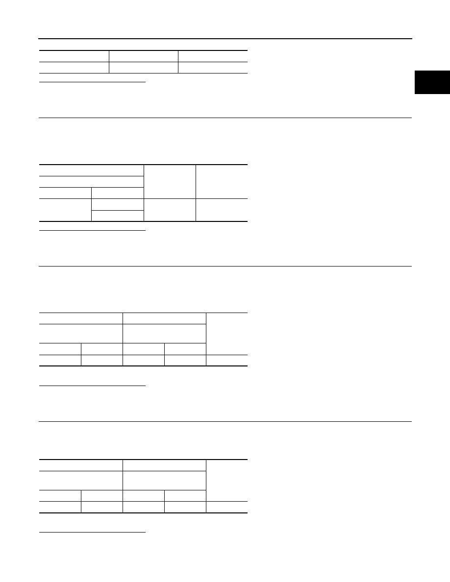
Location
Fuse No.
Capacity
Fuse block (J/B)
7
20A
+
−
Voltage
Engine restart bypass control relay
Connector
Terminal
F98
1
Ground
Battery voltage
5
+
−
Continuity
Engine restart bypass con-
trol relay
ECM
Connector
Terminal
Connector
Terminal
F98
2
F17
83
Existed
+
−
Continuity
Engine restart bypass con-
trol relay
Engine restart bypass relay
Connector
Terminal
Connector
Terminal
E98
3
F146
1
Existed