Qashqai J11. Engine control system (HRA2DDT) - part 19
P2120 APP SENSOR
ECH-289
< DTC/CIRCUIT DIAGNOSIS >
[HRA2DDT]
C
D
E
F
G
H
I
J
K
L
M
A
ECH
N
P
O
4.
Also check harness for short to ground and short to power.
Is the inspection result normal?
YES
>> GO TO 4.
NO
>> Repair or replace error-detected parts.
4.
CHECK ACCELERATOR PEDAL POSITION SENSOR INPUT SIGNAL CIRCUIT
1.
Check the continuity between accelerator pedal position sensor harness connector and ECM harness
connector.
2.
Also check harness for short to ground and short to power.
Is the inspection result normal?
YES
>> GO TO 5.
NO
>> Repair or replace error-detected parts.
5.
CHECK ACCELERATOR PEDAL POSITION SENSOR
ECH-289, "Component Inspection"
Is the inspection result normal?
YES
>> Perform intermittent incident. Refer to
GI-41, "Intermittent Incident"
.
NO
>> Replace accelerator pedal.
6.
CHECK ACCELERATOR PEDAL POSITION SENSOR POWER SUPPLY CIRCUIT
1.
Turn ignition switch OFF.
2.
Disconnect ECM harness connector.
3.
Check the continuity between accelerator pedal position sensor harness connector and ECM harness
connector.
4.
Also check harness for short to ground and short to power.
Is the inspection result normal?
YES
>> Perform the trouble diagnosis for power supply circuit.
NO
>> Repair or replace error-detected parts.
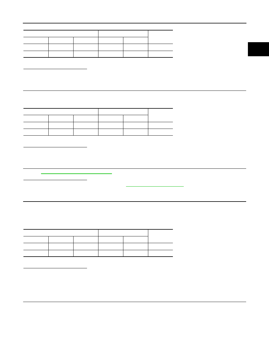
Component Inspection
INFOID:0000000010379170
1.
CHECK ACCELERATOR PEDAL POSITION SENSOR
1.
Reconnect all harness connectors disconnected.
2.
Turn ignition switch ON.
3.
Check the voltage ECM harness connector terminals under the following conditions.
Accelerator pedal position sensor
ECM
Continuity
Sensor
Connector
Terminal
Connector
Terminal
1
E20
2
E9
30
Existed
2
E20
1
E9
21
Existed
Accelerator pedal position sensor
ECM
Continuity
Sensor
Connector
Terminal
Connector
Terminal
1
E20
3
E9
31
Existed
2
E20
6
E9
22
Existed
Accelerator pedal position sensor
ECM
Continuity
Sensor
Connector
Terminal
Connector
Terminal
1
E20
4
E9
27
Existed
2
E20
5
E9
23
Existed