Index Nissan Qashqai J11. Engine control system (R9M). Service and Repair Manual
Search copyright infringement
Content .. 7 8 9 10 ..
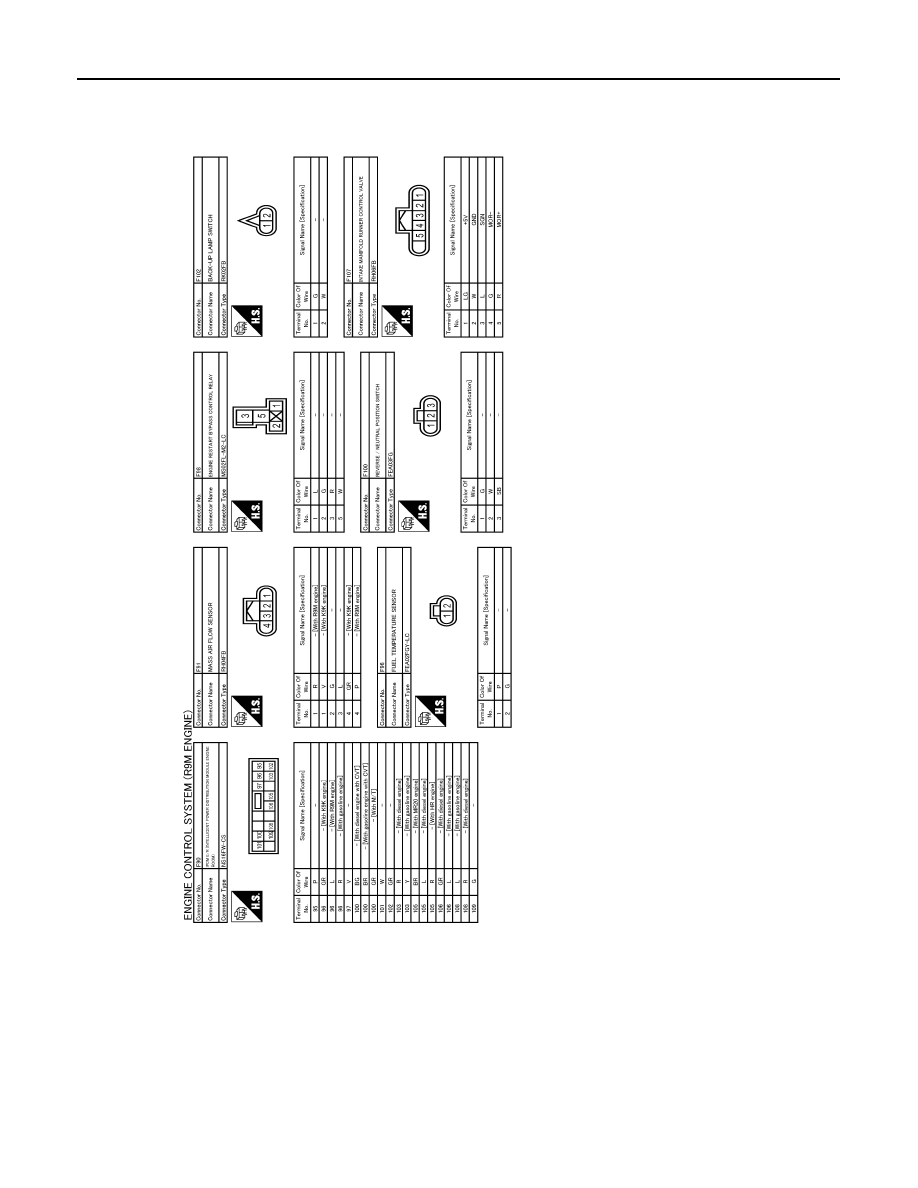
Qashqai J11. Engine control system (R9M) - part 9
EC9-130
< WIRING DIAGRAM >
[R9M]
ENGINE CONTROL SYSTEM
JRBWC6112GB