Qashqai J11. Engine control system (R9M) - part 7
ECM
EC9-97
< ECU DIAGNOSIS INFORMATION >
[R9M]
C
D
E
F
G
H
I
J
K
L
M
A
EC9
N
P
O
138
(L)
134
(R)
Exhaust gas temperature
sensor
Input
[Engine is running]
• Warm-up condition
• Idle speed
0.88 V
[Engine is running]
• Warm-up condition
• Engine speed: 2,000 rpm
0.11 V
140
(W)
29
(B)
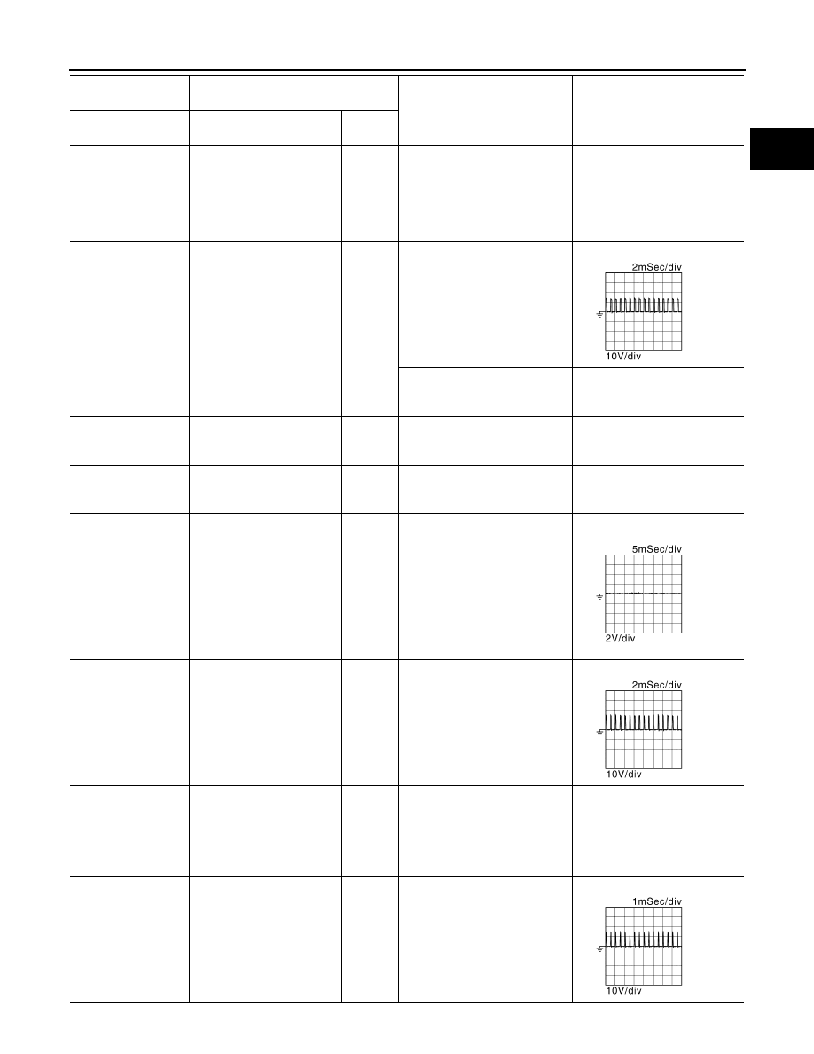
Electric throttle control mo-
tor (-)
Output
[Ignition switch: OFF]
For 20 seconds after turning igni-
tion switch OFF
NOTE:
Repeat several times opening
and shutting after turning ignition
switch OFF.
[Ignition switch: OFF]
More than 20 seconds after turn-
ing ignition switch OFF
0.08 V
141
(V)
—
Sensor ground
(Refrigerant pressure sen-
sor)
—
—
—
142
(G)
—
Sensor ground
(Low pressure EGR temper-
ature sensor)
—
—
—
143
(BR)
29
(B)
Low pressure EGR volume
control valve motor (+)
Output
[Engine is running]
• Engine coolant temperature:
more than 70
°
C (158
°
F)
• Intake air temperature: more
than 20
°
C (68
°
F)
• Idle speed
NOTE:
The duty cycle changes depend-
ing on low pressure EGR volume
control valve operation.
144
(B)
29
(B)
High pressure EGR volume
control valve motor (+)
Input
[Engine is running]
• Engine coolant temperature:
less than 30
°
C (86
°
F)
• Idle speed
NOTE:
The duty cycle changes depend-
ing on high pressure EGR vol-
ume control valve operation.
146
(BR)
142
(G)
Low pressure EGR temper-
ature sensor
Input
[Engine is running]
• Engine coolant temperature:
more than 70
°
C (158
°
F)
• Intake air temperature: more
than 20
°
C (68
°
F)
• Idle speed
0.54 V
Output voltage varies with low
pressure EGR gas temperature.
147
(GR)
29
(B)
Exhaust electric throttle con-
trol motor (-)
Output
[Engine is running]
• Engine coolant temperature:
more than 70
°
C (158
°
F)
• Intake air temperature: more
than 20
°
C (68
°
F)
• Idle speed
Terminal No.
(Wire color)
Description
Condition
Value
(Approx.)
+
−
Signal name
Input/
Output
JSBIA4823ZZ
JSBIA4824ZZ
JSBIA4825ZZ
JSBIA4826ZZ