Nissan Qashqai J11. Manual - part 879
WT-62
< REMOVAL AND INSTALLATION >
[WITH TPMS]
TIRE PRESSURE SENSOR
TIRE PRESSURE SENSOR
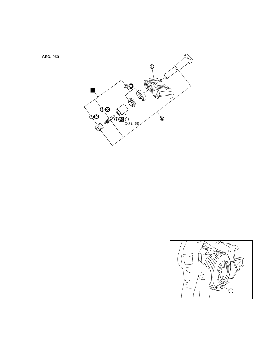
Exploded View
INFOID:0000000010339582
Removal and Installation
INFOID:0000000010339583
REMOVAL
1.
Remove tire assembly. Refer to
WT-60, "Removal and Installation"
2.
Remove valve cap, valve core and then deflate tire.
NOTE:
If the tire is reused, apply a matching mark to the position of the tire road wheel valve hole for the purpose
of wheel balance adjustment after installation.
3.
Remove valve nut retaining tire pressure sensor and allow tire pressure sensor to fall into tire.
4.
Use the tire changer and disengage the tire beads.
CAUTION:
• Verify that the tire pressure sensor (1) is at the bottom of
the tire while performing the above.
• Never damage the road wheel or tire pressure sensor.
5.
Apply bead cream or an equivalent to the tire beads.
6.
Set tire onto the tire changer turntable so that the tire pressure
sensor inside the tire is located close to the road wheel valve
hole.
1.
Tire pressure sensor
2.
Washer/Grommet seal
3.
Valve nut
4.
Valve core
5.
Valve cap
6.
Valve stem assembly
Refer to
for symbols not described on the above.
JMEIA0243GB
JPEIC0104ZZ