Nissan Qashqai J11. Manual - part 851


  Index      Nissan     Nissan Qashqai J11 - Service and Repair Manual


Search            


Content   ..  849  850  851  852   ..


Nissan Qashqai J11. Manual - part 851


REAR DRIVE SHAFT

RAX-15

< REMOVAL AND INSTALLATION >

[4WD]

C

E

F

G

H

I

J

K

L

M

A

B

RAX

N

O

P

3.

Remove disc rotor.

4.

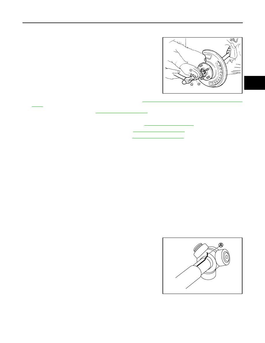
Remove cotter pin, then loosen hub lock nut.

5.

Patch hub lock nut with a piece of wood. Hammer the wood to
disengage wheel hub and bearing assembly from drive shaft.
Remove the hub lock nut. 

CAUTION:

• Never place drive shaft joint at an extreme angle. Also be

careful not to overextend slide joint.

• Never allow drive shaft to hang down without support for

housing (or joint sub-assembly), shaft and the other parts.

NOTE:
Using a suitable puller if the wheel hub and bearing assembly
and drive shaft cannot be separated even after performing the
above procedure.

6.

Remove wheel sensor from axle housing. Refer to  

BRC-139, "REAR WHEEL SENSOR : Exploded

View"

.

7.

Remove stabilizer link. Refer to 

RSU-16, "Exploded View"

.

8.

Set suitable jack under suspension arm.

9.

Remove shock absorber from suspension arm. Refer to 

RSU-9, "Exploded View"

.

10. Remove upper link from suspension arm. Refer to 

RSU-13, "Exploded View"

.

11. Remove lower link from suspension arm. Refer to 

RSU-13, "Exploded View"

.

12. Remove drive shaft from final drive assembly.

INSTALLATION

Note the following, and install in the reverse order of removal.
• Perform final tightening of bolts and nuts at suspension arm (rubber bushing), under unladen conditions with

tires on level ground.

Disassembly and Assembly

INFOID:0000000010297914

DISASSEMBLY

Final Drive Side

1.

Fix shaft with a vise.

CAUTION:

Protect shaft using aluminum or copper plates when fixing with a vise.

2.

Remove boot bands, and then remove boot from housing.

3.

Put matching marks on housing and shaft.

CAUTION:

Use paint or an equivalent for matching marks. Never scratch the surface.

4.

Put matching marks (A) on the spider assembly and shaft.

CAUTION:

Use paint or an equivalent for matching marks. Never
scratch the surface.

JPDIF0003ZZ

JPDIF0006ZZ

RAX-16

< REMOVAL AND INSTALLATION >

[4WD]

REAR DRIVE SHAFT

5.

Remove snap ring (1), and then remove spider assembly from
shaft.

6.

Remove boot from shaft.

7.

Remove circular clip housing.

8.

Remove dust shield to housing.

9.

Remove old grease on housing with paper towels.

Wheel Side

1.

If sensor rotor needs to be removed, use a bearing replacer (A)
and puller (B). Refer to  

BRC-141, "REAR SENSOR ROTOR :

Removal and Installation - Rear Sensor Rotor"

.

2.

Fix shaft with a vise.

CAUTION:

Protect shaft using aluminum or copper plates when fixing with a vise.

3.

Remove boot bands. Then remove boot from joint sub-assembly.

4.

Screw the drive shaft puller (A) 30 mm (1.18 in) or more into the
thread of joint sub-assembly, and pull joint sub-assembly with a
sliding hammer (B) from shaft.

CAUTION:

• If joint sub-assembly cannot be removed after five or

more unsuccessful attempts, replace shaft and joint sub
assembly as a set.

• Align sliding hammer and drive shaft and remove them by

pulling directory.

5.

Remove boot from shaft.

6.

Remove circular clip.

CAUTION:

Never reuse circular clip.

7.

While rotating ball cage, clean old grease on joint sub-assembly with paper towels.

ASSEMBLY

Final drive Side

1.

Wrap serrated part of shaft with tape (A). Install boot band and
boot to shaft. Be careful not to damage boot.

CAUTION:

Never reuse boot and boot band.

2.

Remove the tape wrapped around the serrated on shaft.

JPDIF0014ZZ

JPDIG0016ZZ

JPDIF0015ZZ

JPDIF0009ZZ

REAR DRIVE SHAFT

RAX-17

< REMOVAL AND INSTALLATION >

[4WD]

C

E

F

G

H

I

J

K

L

M

A

B

RAX

N

O

P

3.

To install the spider assembly (1), align it with the matching
marks (A) that were on the shaft (2) during the removal, and
direct the serration mounting surface (B) to the shaft.

4.

Secure spider assembly onto shaft with snap ring (1).

5.

Apply the appropriate amount of grease onto housing and slid
surface.

6.

Assemble the housing onto spider assembly, and apply the bal-
ance of the specified amount grease.

7.

Align matching marks painted when housing were removed.

8.

Install boot securely into grooves (indicated by “*” marks) shown
in the figure.

CAUTION:

If there is grease on boot mounting surfaces (indicated by
“*” marks) of shaft or housing, boot may be removed.
Remove all grease from the surfaces.

9.

To prevent from deformation of the boot, adjust the boot installa-
tion length to the value shown below (L) by inserting the suitable
tool into the inside of boot from the large diameter side of boot
and discharging inside air.

CAUTION:

• If the boot installation length exceeds the standard, it may cause breakage in boot.
• Be careful not to touch the inside of the boot with the tip of tool.

10. Secure large and small ends of boot with new boot bands as

shown in the figure. 

CAUTION:

Never reuse boot band.

11. Secure housing and shaft, and then make sure that they are in

the correct position when rotating boot. Install them with new
boot band when the mounting positions become incorrect.

12. Install dust shield to housing.

CAUTION:

Never reuse dust shield.

13. Install circular clip to housing.

CAUTION:

Never reuse circular clip.

Wheel Side

JPDIF0017ZZ

Standard

Grease amount

: Refer to 

RAX-21, "Drive 

Shaft"

.

Standard

Boots installed 
length (L)

: Refer to 

RAX-21, "Drive 

Shaft"

.

JPDIF0014ZZ

JPDIF0032ZZ

PDIA1188J

RAX-18

< REMOVAL AND INSTALLATION >

[4WD]

REAR DRIVE SHAFT

1.

If sensor rotor (1) is removed, use a drift (A) (SST: KV38100500)
and collar (B) (SST: KV40101840) to press in a new one.

2.

Fill serration slot joint sub-assembly (1) with NISSAN genuine
grease or equivalent until the serration slot and ball groove
become full to the brim.

CAUTION:

After applying grease, use a shop cloth to wipe off old
grease that has oozed out.

3.

Wrap serrated part of shaft with tape (A). Install boot band and
boot to shaft. Be careful not to damage boot.

CAUTION:

Never reuse boot and boot band.

4.

Remove the tape wrapped around the serrated on shaft.

5.

Position circular clip on groove at the shaft edge.

CAUTION:

Never reuse circular clip.
NOTE:
Drive joint inserter is recommended when installing circular clip.

6.

Align both center axles of the shaft edge and joint sub-assembly.
Then assemble shaft with circular clip joint sub-assembly.

7.

Install joint sub-assembly to shaft using plastic hammer.

CAUTION:

Confirm that joint sub-assembly is correctly engaged while
rotating drive shaft.

8.

Apply the balance of the specified amount of grease into the
boot inside from large diameter side of boot.

PDIA1182J

JPDIF0008ZZ

Standard

Grease amount

: Refer to 

RAX-21, "Drive 

Shaft"

.

JPDIF0009ZZ

RAC0049D


Content   ..  849  850  851  852   ..