Nissan Qashqai J11. Manual - part 703


  Index      Nissan     Nissan Qashqai J11 - Service and Repair Manual


Search            


Content   ..  701  702  703  704   ..


Nissan Qashqai J11. Manual - part 703


CONTROL CABLE

TM-387

< REMOVAL AND INSTALLATION >

[CVT: RE0F10D]

C

E

F

G

H

I

J

K

L

M

A

B

TM

N

O

P

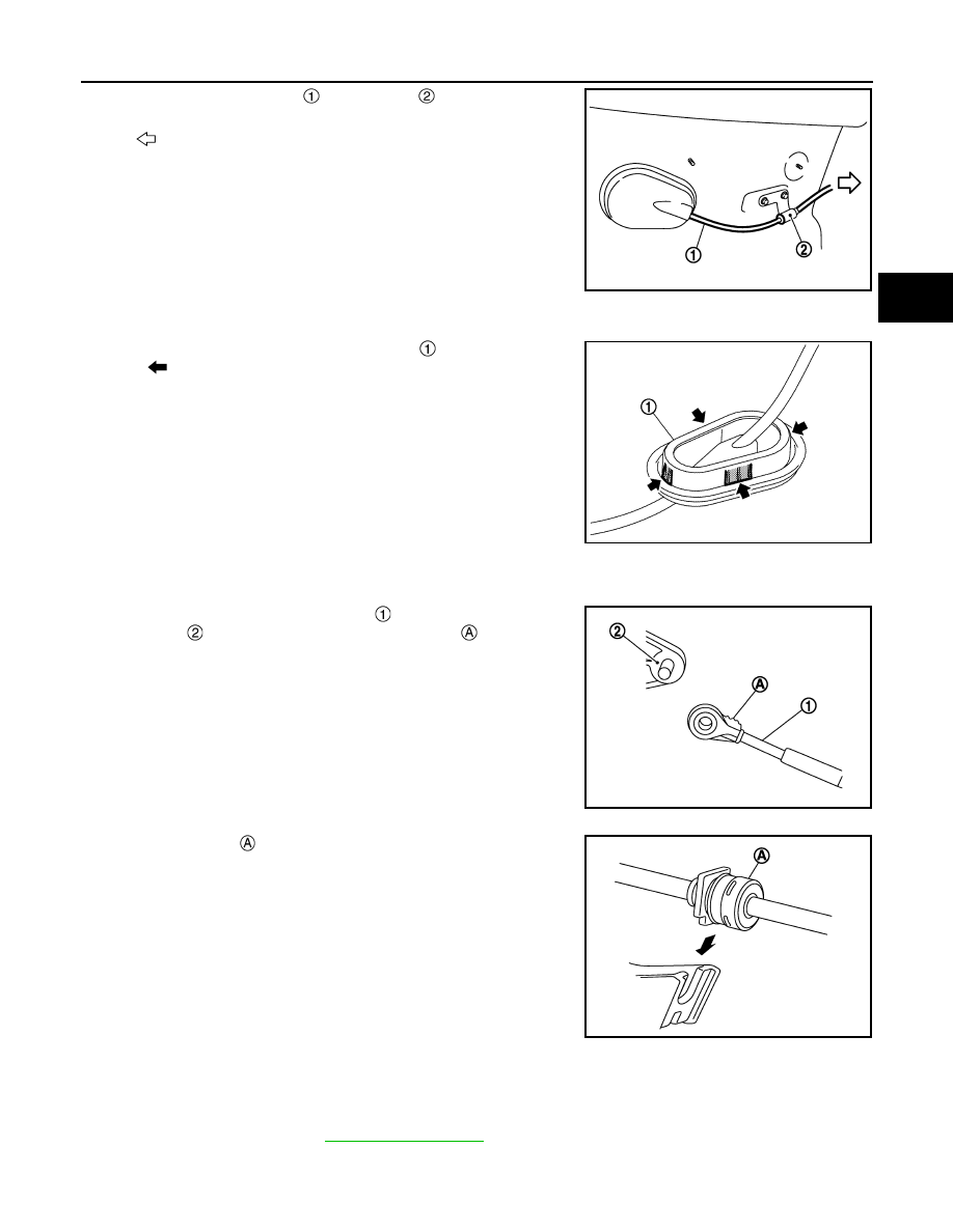
13. Remove the control cable 

 from bracket 

.

14. Remove the control cable from the vehicle.

INSTALLATION

Note the followings and install in the reverse order of removal.
• From below the vehicle, press the grommet 

 into place until the

pawls (

) make a click sound.

CAUTION:

• Place the grommet on the floor, then fasten it in place from

below the vehicle.

• Check that pulling down on the grommet does not discon-

nect it.

• Pay attention to the following when connecting the control cable to the CVT shift selector.
1.

Shift the selector lever and Manual lever to “P” position. 

2.

When connecting the control cable 

 to the CVT shift selector

assembly 

, face the grooved surface of the rib 

 up and insert

the control cable until it stops.

3.

Install the socket 

 onto the CVT shift selector assembly.

CAUTION:

• Place the socket onto the CVT shift selector assembly,

then fasten it in place from above.

• Check that the pulling on the socket does not disconnect

it.

Inspection and Adjustment

INFOID:0000000010668192

ADJUSTMENT AFTER INSTALLATION

Adjust the CVT position. Refer to 

TM-287, "Adjustment"

.

INSPECTION AFTER ADJUSTMENT

: Vehicle front

JPDIA0107ZZ

JSDIA5182ZZ

JSDIA1624ZZ

JSDIA1810ZZ

TM-388

< REMOVAL AND INSTALLATION >

[CVT: RE0F10D]

CONTROL CABLE

Check the CVT shift selector position after the adjustment. Refer to 

TM-287, "Inspection"

.

KEY INTERLOCK CABLE

TM-389

< REMOVAL AND INSTALLATION >

[CVT: RE0F10D]

C

E

F

G

H

I

J

K

L

M

A

B

TM

N

O

P

KEY INTERLOCK CABLE

Exploded View

INFOID:0000000010668193

Removal and Installation

INFOID:0000000010668194

REMOVAL

CAUTION:

Always apply the parking brake before performing removal and installation.
1.

Remove the lower instrument panel (driver side) and steering column cover. Refer to 

IP-13, "Removal and

Installation"

.

2.

Remove the center console. Refer to 

IP-19, "Removal and Installation"

.

3.

Press the pawls 

 of the key interlock cable slider 

 while slid-

ing it in the direction of the casing cap 

, and separate the

adjusting holder 

 and slider.

4.

Remove the key interlock cable from the shift selector. 

5.

Lift the clip 

 in the direction of the arrow (


) and remove in

the direction of the arrow (


).

6.

Remove the key interlock cable from the key cylinder.

7.

Disengage the clip and disconnect the key interlock cable from
the vehicle.

Shift selector assembly

Clip

Key interlock cable

Clip

Key cylinder

JSDIA5227ZZ

:Key interlock rod

JSDIA1797ZZ

: Key interlock cable

: Key cylinder

JSDIA1798ZZ

TM-390

< REMOVAL AND INSTALLATION >

[CVT: RE0F10D]

KEY INTERLOCK CABLE

INSTALLATION

1.

Move the shift selector to "P" position.

2.

Turn the ignition switch to ACC or ON position.

3.

Install the holder of key interlock cable to key cylinder.

4.

Install the clip 

 in the direction of the arrow (


) and push it

in the direction of the arrow (


).

5.

Turn the ignition switch to LOCK position.

6.

Install the adjusting holder 

 onto the key interlock rod 

, then

install the casing cap 

 onto the shift selector cable bracket 

.

CAUTION:

• When installing the key interlock cable, do not bend or

twist the cable forcefully.

• After connecting the key interlock cable to the shift selec-

tor cable bracket, be sure to check that the casing cap is
completely fastened to the cable bracket. If the casing cap
is easily displaced, replace the key interlock cable.

7.

Slide the key interlock cable slider 

 toward the key interlock

rod 

 side and install the adjusting holder 

 and key interlock

rod.

CAUTION:

• Never squeeze the pawls on the key interlock cable slider

when holding the slider.

• Never apply force in a perpendicular direction to the key

interlock rod when sliding the slider.

8.

Install the center console. Refer to 

IP-19, "Removal and Installa-

tion"

.

9.

Install the lower instrument panel (driver side) and steering col-
umn cover. Refer to 

IP-13, "Removal and Installation"

.

Inspection

INFOID:0000000010668195

INSPECTION AFTER INSTALLATION

• Check the CVT position. If a malfunction is found, adjust the CVT position. Refer to 

TM-287, "Inspection"

.

• The key can be removed only when the selector lever is in the “P” position.
• It must not be possible to turn the ignition switch to LOCK when the selector lever is not in the “P” position.

: Key interlock cable

: Key cylinder

JSDIA3589ZZ

JSDIA1799ZZ

JSDIA2644ZZ


Content   ..  701  702  703  704   ..