Nissan Qashqai J11. Manual - part 702
CVT SHIFT SELECTOR
TM-383
< REMOVAL AND INSTALLATION >
[CVT: RE0F10D]
C
E
F
G
H
I
J
K
L
M
A
B
TM
N
O
P
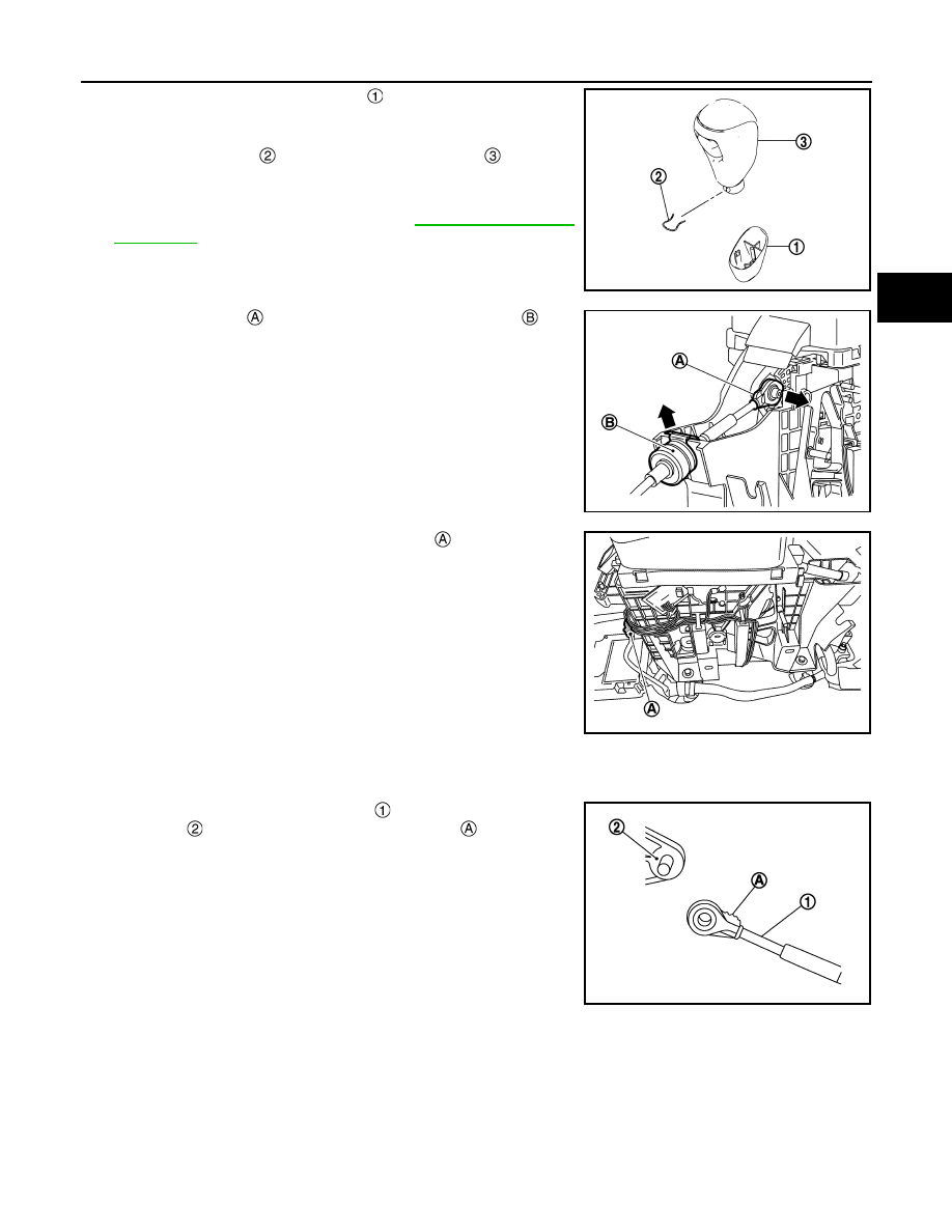
a.
Slide the selector lever knob cover
down.
CAUTION:
Never damage the knob cover.
b.
Pull out the lock pin
from the selector lever knob
.
c.
Pull the selector lever knob and the selector lever knob cover
upwards to remove them.
6.
Remove the center console. Refer to
.
7.
Shift the selector lever to “P” position.
8.
Disconnect the tip
of control cable and remove socket
from
the CVT shift selector assembly.
9.
Disconnect the CVT shift selector connector
.
10. Remove the CVT shift selector assembly from the vehicle.
INSTALLATION
Note the followings and install in the reverse order of removal.
• Pay attention to the following when connecting the control cable to the CVT shift selector assembly.
1.
When connecting the control cable
to the CVT shift selector
assembly
, face the grooved surface of the rib
up and insert
the control cable until it stops.
NOTE:
Apply multi-purpose grease to control cable eye before installa-
tion.
JSDIA2778ZZ
JSDIA4220ZZ
JSDIA5384ZZ
JSDIA1624ZZ