Nissan Qashqai J11. Manual - part 625


  Index      Nissan     Nissan Qashqai J11 - Service and Repair Manual


Search            


Content   ..  623  624  625  626   ..


Nissan Qashqai J11. Manual - part 625


POSITION SWITCH

TM-75

< DTC/CIRCUIT DIAGNOSIS >

[6MT: RS6F95R]

C

E

F

G

H

I

J

K

L

M

A

B

TM

N

O

P

DTC/CIRCUIT DIAGNOSIS

POSITION SWITCH

BACK-UP LAMP SWITCH

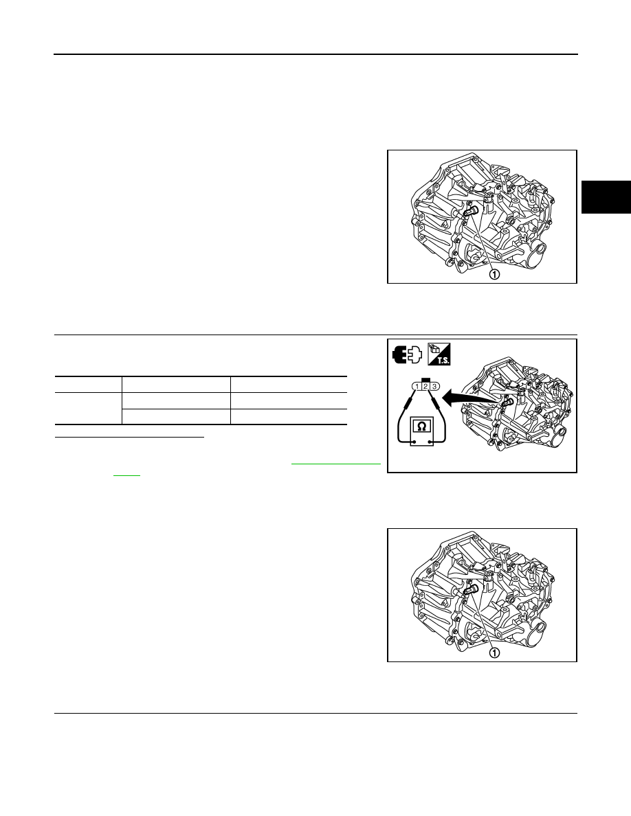
BACK-UP LAMP SWITCH : Component Parts Location

INFOID:0000000010428763

BACK-UP LAMP SWITCH : Component Inspection

INFOID:0000000010428764

1.

CHECK BACK-UP LAMP SWITCH

Check continuity between position switch terminals with control lever
turned to 1st to 6th and reverse position.

Is the inspection result normal?

YES

>> INSPECTION END

NO

>> Replace position switch. Refer to 

TM-91, "Exploded

View"

PARK/NEUTRAL POSITION (PNP) SWITCH

PARK/NEUTRAL POSITION (PNP) SWITCH : Component Parts Location

INFOID:0000000010428765

PARK/NEUTRAL POSITION (PNP) SWITCH : Component Inspection

INFOID:0000000010428766

1.

CHECK PARK/NEUTRAL POSITION (PNP) SWITCH

1

: Position switch

E1DIA0340ZZ

Terminals

Gear position

Continuity

1 – 2

Reverse

Existed

Except reverse

Not existed

E1DIA0344GB

1

: Position switch

E1DIA0340ZZ

TM-76

< DTC/CIRCUIT DIAGNOSIS >

[6MT: RS6F95R]

POSITION SWITCH

Check continuity between position switch terminals with control lever
turned to 1st to 6th and reverse position.

Is the inspection result normal?

YES

>> INSPECTION END

NO

>> Replace position switch. Refer to 

TM-91, "Exploded

View"

.

Terminals

Gear position

Continuity

2 – 3

Neutral

Existed

Except neutral

Not existed

E1DIA0345GB

NOISE, VIBRATION AND HARSHNESS (NVH) TROUBLESHOOTING

TM-77

< SYMPTOM DIAGNOSIS >

[6MT: RS6F95R]

C

E

F

G

H

I

J

K

L

M

A

B

TM

N

O

P

SYMPTOM DIAGNOSIS

NOISE, VIBRATION AND HARSHNESS (NVH) TROUBLESHOOTING

NVH Troubleshooting Chart

INFOID:0000000010428767

Use the chart below to help you find the cause of the symptom. The numbers indicate the order of the inspec-
tion. If necessary, repair or replace these parts.

Reference page

TM-91

TM-91

TM-83

TM-91

TM-91

SUSPECTED PARTS
(Possible cause)

OIL

 (Oil 

lev

e

l is

 l

o

w

.)

OI

L (W

ro

ng

 oi

l.

)

OIL

 (Oil 

lev

e

l is

 h

igh

.)

GASKET

 (Damaged)

OIL SEAL (W

orn or 

damaged)

O-RING (W

orn

 or 

da

ma

ge

d)

SHIF

T CONTROL L

INKAGE 

(W

o

rn)  


SHIF

T FORK (W

o

rn)

GEAR (W

o

rn o

r da

m

age

d)

BEAR

ING

 (W

orn

 o

da

ma

ge

d)

BAUL

K

 RING (W

orn

 o

r da

ma

ge

d)

INSE

R

T

 S

P

RING (Dam

ag

ed

)

Symptoms

Noise

1

2

3

3

Oil  leakage

3

1

2

2

2

Hard to shift or will not shift

1

1

2

3

3

Jumps out of gear

1

2

2

TM-78

< PRECAUTION >

[6MT: RS6F95R]

PRECAUTIONS

PRECAUTION

PRECAUTIONS

Precaution for Procedure without Cowl Top Cover

INFOID:0000000010497457

When performing the procedure after removing cowl top cover, cover
the lower end of windshield with urethane, etc to prevent damage to
windshield.

Precautions for Removing Battery Terminal

INFOID:0000000010508550

• With the adoption of Auto ACC function, ACC power is automatically supplied by operating the intelligent key

or remote keyless entry or by opening/closing the driver side door. In addition, ACC power is supplied even
after the ignition switch is turned to the OFF position, i.e. ACC power is supplied for a certain fixed time.

• When disconnecting the 12V battery terminal, turn off the ACC

power before disconnecting the 12V battery terminal, observing
“How to disconnect 12V battery terminal” described below.
NOTE:
Some ECUs operate for a certain fixed time even after ignition
switch is turned OFF and ignition power supply is stopped. If the
battery terminal is disconnected before ECU stops, accidental DTC
detection or ECU data damage may occur.

•  For vehicles with the 2-batteries, be sure to connect the main bat-

tery and the sub battery before turning ON the ignition switch.
NOTE:
If the ignition switch is turned ON with any one of the terminals of
main battery and sub battery disconnected, then DTC may be detected.

•  After installing the 12V battery, always check "Self Diagnosis Result" of all ECUs and erase DTC.

NOTE:
The removal of 12V battery may cause a DTC detection error.

HOW TO DISCONNECT 12V BATTERY TERMINAL

Disconnect 12V battery terminal according to Instruction 1 or Instruction 2 described below.
For vehicles parked by ignition switch OFF, refer to Instruction 2.

INSTRUCTION 1

1.

Open the hood.

2.

Turn key switch to the OFF position with the driver side door opened.

3.

Get out of the vehicle and close the driver side door.

4.

Wait at least 3 minutes. For vehicle with the engine listed below, remove the battery terminal after a lapse
of the specified time.

CAUTION:

PIIB3706J

SEF289H

D4D engine

: 20 minutes

HRA2DDT

: 12 minutes

K9K engine

: 4 minutes

M9R engine

: 4 minutes

R9M engine

: 4 minutes

V9X engine

: 4 minutes


Content   ..  623  624  625  626   ..