Nissan Qashqai J11. Manual - part 2171


  Index      Nissan     Nissan Qashqai J11 - Service and Repair Manual


Search            


Content   ..  2169  2170  2171  2172   ..


Nissan Qashqai J11. Manual - part 2171


DAS-98

< BASIC INSPECTION >

[DRIVER ASSISTANCE SYSTEM]

CAMERA AIMING ADJUSTMENT

Work Procedure (Camera Aiming Adjustment)

INFOID:0000000010609511

CAUTION:

Perform the adjustment under unloaded vehicle condition.

1.

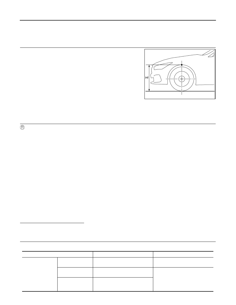
CHECK VEHICLE HEIGHT

Measure both side of front wheelarch height (Hf). Then calculate
“Dh”.

CAUTION:

Be sure to measure wheelarch height correctly.
NOTE:
“Dh” may be calculated as a minus value.

>> GO TO 2.

2.

CAMERA AIMING ADJUSTMENT

With CONSULT

CAUTION:

Operate CONSULT outside the vehicle, and close all the doors. (To retain vehicle attitude appropri-
ately)
1.

Select “Work Support” on “LANE CAMERA” with CONSULT.

2.

Select “AUTO AIM”.

3.

Confirm the following items;

-

The target should be accurately placed.

-

The vehicle should be stopped.

4.

Select “Start” to perform camera aiming.

CAUTION:

• Never select “Start” when the target is not accurately placed.
• Wait 5 seconds or more after selecting “Start”.

5.

Input the following parameters, and then select “Start”.

-

Htu: 1501 (mm)

-

Htl: 1299 (mm)

-

Dt: 2800 (mm)

-

Ts: 101 (mm)

-

Dbt: 956 (mm)

-

VP: 2 (RHD models for Europe)/4 (LHD models for Europe)/6 (for Russia)/7 (for Australia) 

6.

Confirm the displayed item.

Is “Normally Completed” displayed?

YES

>> Select “End” to close the aiming adjustment procedure. Then GO TO 4.

NO

>> GO TO 3.

3.

INCOMPLETE CAUSE CONFIRMATION 

1.

Perform the following services according to the displayed message.

Dh [mm] = (Hfl + Hfr) 

÷

 2 

 763

where,

Hfl: Front left wheelarch height [mm]

Hfr: Front right wheelarch height [mm]

JSOIA1046GB

Displayed message

Possible cause

Service procedure

Stop

Temporary malfunction in internal pro-
cessing of the front camera unit.

Go back to step 1.

00H Routine not acti-
vated

Front camera unit malfunction.

Position the target appropriately again. 
Then perform the aiming again.

10H Writing error

• Temporary malfunction in internal 

processing of the front camera unit.

• Front camera unit malfunction.

DAS

CAMERA AIMING ADJUSTMENT

DAS-99

< BASIC INSPECTION >

[DRIVER ASSISTANCE SYSTEM]

C

D

E

F

G

H

I

J

K

L

M

B

N

P

A

NOTE:
Replace camera unit if “00H Routine not activated” or “Writing error is detected.” are repeatedly indicated
during the above two services are performed.

2.

Confirm that “Normally completed” is displayed and then select “End” to close the adjustment procedure.

>> GO TO 4.

4.

PERFORM SELF-DIAGNOSIS

With CONSULT

Perform self-diagnosis of front camera unit with CONSULT.

Is any DTC detected?

YES

>> Perform diagnosis on the detected DTC and repair or replace the applicable item. Refer to 

DAS-

61, "DTC Index"

.

NO

>> WORK END

Work Procedure (Target Mark Sample)

INFOID:0000000010609512

Adjust the scale so that the item is the same size as the following, and print.
• Target length (L): 202 mm
• Target width (W): 303 mm

CAUTION:

• Never allow a clearance on the black and white boundary.

0 – 16

• A target is not -yet-placed.

(Front camera unit cannot detect the 
target.)

• The position of the targets is not cor-

rect.

• The position of the front camera unit 

is not correct.

• Inappropriate work environment.
• Inappropriate vehicle condition.
• Input value is not correct against ac-

tual setting position.

Position the target appropriately again. 
Then perform the aiming again.

Abnormally complet-

ed.

Displayed message

Possible cause

Service procedure

DAS-100

< BASIC INSPECTION >

[DRIVER ASSISTANCE SYSTEM]

CAMERA AIMING ADJUSTMENT

• Never apply tape to target surface.

JSOIA0633ZZ

DAS

CALIBRATING CAMERA IMAGE (AROUND VIEW MONITOR)

DAS-101

< BASIC INSPECTION >

[DRIVER ASSISTANCE SYSTEM]

C

D

E

F

G

H

I

J

K

L

M

B

N

P

A

CALIBRATING CAMERA IMAGE (AROUND VIEW MONITOR)

Description

INFOID:0000000010619788

• Always perform the rear camera calibration after removing and installing or replacing the rear camera.
• Always perform the rear camera calibration after replacing the around view monitor control unit.

CAUTION:

• Place the vehicle on level ground when the calibration is operated.
• Follow the CONSULT when performing the calibration. (Rear camera calibration cannot be operated

without CONSULT.)

Work Procedure (Preparation)

INFOID:0000000010619789

1.

PERFORM SELF-DIAGNOSIS

Perform self-diagnosis of the camera control unit with CONSULT (AVM).

Is any DTC detected?

Except “U1308”>>Perform diagnosis on the detected DTC and repair or replace the applicable item. Refer to

DAS-49, "DTC Index"

.

“U1308” or no DTC>>GO TO 2.

2.

PREPARATION BEFORE REAR CAMERA CALIBRATION

1.

Perform pre-inspection for diagnosis. Refer to 

DAS-82, "Inspection Procedure"

.

2.

Adjust the tire pressure to the specified pressure value.

3.

Maintain no-load in vehicle.

4.

Check if coolant and engine oil are filled up to correct level and fuel tank is full.

5.

Shift the selector lever to “P” position and release the parking brake.

6.

Clean the rear camera.

>> GO TO 3.

3.

PREPARATION OF CALIBRATION TARGET MARK

1.

Prepare six sheets of white paper and black paper, respectively, with dimensions of 250 mm (9.84 in) 

×

250 mm (9.84 in) to create a left target, right target, and center target.
NOTE:
Correct the magnification of print and print the target mark sample in the service manual on the blackpa-
per. Refer to 

DAS-105, "Work Procedure (Target Mark Sample)"

.

2.

Tape two sheets of black paper and two sheets of white paper
together to make a target of 500 mm (19.69 in) 

×

 500 mm (19.69

in).

NOTE:
Use a transparent tape.

3.

Create two more targets according to step 2.

W

:250 mm (9.84 in)

L

:250 mm (9.84 in)

JSOIA0635ZZ


Content   ..  2169  2170  2171  2172   ..