Nissan Qashqai J11. Manual - part 2169


  Index      Nissan     Nissan Qashqai J11 - Service and Repair Manual


Search            


Content   ..  2167  2168  2169  2170   ..


Nissan Qashqai J11. Manual - part 2169


DAS-90

< BASIC INSPECTION >

[DRIVER ASSISTANCE SYSTEM]

DISTANCE SENSOR ALIGNMENT

DISTANCE SENSOR ALIGNMENT

Description

INFOID:0000000010608813

OUTLINE OF RADAR ALIGNMENT PROCEDURE

• A 4-wheel vehicle alignment must be performed before proceeding with radar alignment procedure.
• Always perform the radar alignment after removing and installing or replacing the distance sensor.

WARNING:

Radio waves could adversely affect electric medical equipment. Those who use a pacemaker should
contact the electric medical equipment manufacturer for the possible influences before use.

CAUTION:

The system does not operate normally unless the radar alignment is performed. Always perform it. 
1.

Preparation, refer to 

DAS-90, "Work Procedure (Preparation)"

2.

Set the ICC target board (SST: KV99112700) to the correct position in front of the vehicle. Refer to 

DAS-

92, "Work Procedure (Setting The ICC Target Board)"

.

3.

Set the radar alignment mode (“MILLIWAVE RADAR ADJUST” on “Work support”) with CONSULT, and
then perform the adjustment according to the display. Refer to 

DAS-93, "Work Procedure (Radar Align-

ment)"

.

CAUTIONARY POINT FOR RADAR ALIGNMENT PROCEDURE

CAUTION:

• For radar alignment procedure, choose a level location with a few meter of working space in front

and surrounding the vehicle.

• Vehicle must be stationary and unoccupied during the whole alignment procedure.
• Any slight vibration during the alignment procedure can cause the test to fail. If this happens, you

will have to restart the alignment process.

• The ignition switch must be in the ON position.
• The battery voltage must not fall below 12 volts during the whole alignment procedure. Failure to

maintain adequate battery voltage will cause the test to fail. If this happens, you will have to restart
the alignment process.

• The ICC target board must be set in front of the vehicle facing the sensor.
• Adjust the radar alignment with CONSULT. (The radar alignment procedure cannot be adjusted with-

out CONSULT.)

• Never enter the vehicle during radar alignment.
• Never block the area between the radar and the ICC target board at any time during the alignment

process.

• Accurate steering wheel setting is crucial. Once set, do not disturb the steering wheel for the

remainder of the alignment procedure.

• For proper system operation and adjustment, all vehicle wheels must be of the same size.

Work Procedure (Preparation)

INFOID:0000000010608814

1.

ADVANCE PREPARATION FOR RADAR ALIGNMENT

1.

Adjust all tire pressure to the specified value.

2.

Empty the vehicle. (Remove any luggage from the passenger compartment, trunk room, etc.) 

3.

Shift the selector lever to “P” position, and release the parking brake. 

4.

Fully fill the fuel tank, and then check that the coolant and oils are filled up to correct level.
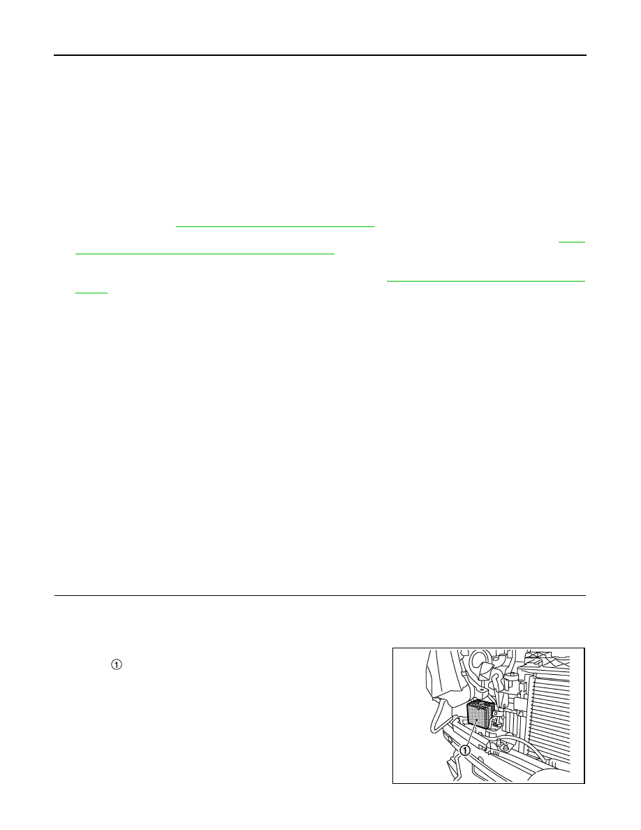
5.

Clean the right front side of the fascia in front of the distance
sensor .
NOTE:
Check the distance sensor surface is clean.

>> GO TO 2.

JMOIA0055ZZ

DAS

DISTANCE SENSOR ALIGNMENT

DAS-91

< BASIC INSPECTION >

[DRIVER ASSISTANCE SYSTEM]

C

D

E

F

G

H

I

J

K

L

M

B

N

P

A

2.

PREPOSITION TARGET BOARD

Adjust the height of distance sensor 

 center position and height of the ICC target board 

 center position.

>> GO TO 3.

3.

RADAR ALIGNMENT OPERATION AREA

Position the vehicle in a place that is level and where 

 area can be secured.

NOTE:

 is a no object zone.

>> Go to 

DAS-92, "Work Procedure (Setting The ICC Target Board)"

H

: 709.2 mm (27.92 in)

JMOIA0057ZZ

W

: 3000 mm (118.11 in)

L

: 2000 mm (78.74 in)

H

: 2000 mm (78.74 in)

JMOIA0058ZZ

DAS-92

< BASIC INSPECTION >

[DRIVER ASSISTANCE SYSTEM]

DISTANCE SENSOR ALIGNMENT

Work Procedure (Setting The ICC Target Board)

INFOID:0000000010608815

DESCRIPTION

Accurate adjustment of the radar alignment requires that the ICC target board be accurately positioned.

CAUTION:

If the radar alignment is adjusted with the ICC target board in the incorrect position, the FEB system
does not function normally. 

1.

ICC TARGET BOARD HEIGHT ADJUSTMENT

Adjust the base of ICC target board to approximately 30 mm from the ground.

>> GO TO 2.

2.

PREPARATION OF SETTING ICC TARGET BOARD (1)

1.

Mark points “A”, “B”, “C” and “D”at the center of the lateral sur-
face of each wheels.
NOTE:
Hang a string with a cone from the fender so as to pass through
the center of wheel, and then mark a point at the center of the
lateral surface of the wheel.

2.

Draw line “LH” passing through points “A” and “B” on the left side
of vehicle. 
NOTE:
Approximately 2 m (6.56 ft) or more from the front end of vehi-
cle.

3.

Mark point “E” on the line “LH” at the positions 2032.1 mm
(80.00 in) from point “A”.

4.

Draw line “RH” passing through points “C” and “D” on the right side of vehicle in the same way as step 2.
NOTE:
Approximately 2 m (6.56 ft) or more from the front end of vehicle.

5.

Mark point “F” on the line “RH” at the positions 2032.1 mm (80.00 in) from point “C”.

6.

Draw line “FW” passing through the points “E” and “F” on the front side of vehicle.

7.

Mark point “X” at the center of point “E” and “F” on the line “FW”.

CAUTION:

Make sure that “E” to “X” is equal to “F” to “X”.

“A” – “E” (“C” – “F”) 

: 2032.1 mm (80.00 in)

PKIB4694E

PKIB7667E

DAS

DISTANCE SENSOR ALIGNMENT

DAS-93

< BASIC INSPECTION >

[DRIVER ASSISTANCE SYSTEM]

C

D

E

F

G

H

I

J

K

L

M

B

N

P

A

8.

With point “X” as the starting point, mark point “G” on “F” point
side 293.9 mm.

>> GO TO 3.

3.

SETTING ICC TARGET BOARD

Place the center of ICC target board on point “G” at line “E-F” and install the ICC target board. 

CAUTION:

For performing the radar alignment correctly, securely install (ICC target board) to be parallel with the
“E-F” line.

>> GO TO 4.

4.

CHECK THE ICC TARGET BOARD INSTALLATION AREA

Do not place anything other than ICC target board in the space shown in the figure (view from top). 

>> Go to 

DAS-93, "Work Procedure (Radar Alignment)"

Work Procedure (Radar Alignment)

INFOID:0000000010608816

DESCRIPTION

The radar alignment is performed automatically with CONSULT.

CAUTION:

Perform all necessary work for radar alignment until the adjustment completes as shown in the proce-
dure. If the procedure does not complete, the FEB system is inoperable.

1.

PERFORM RADAR ALIGNMENT

1.

Start the engine.

2.

Connect CONSULT and select “Work support” of “LASER/RADAR”.

3.

Select “MILLIWAVE RADAR ADJUST” after the “Work support” screen is displayed.
NOTE:
Confirm the following items;
• The target should be accurately placed.

L1

: 2032.1 mm (80.00 in)

L2

: 293.9 mm (11.57 in)

JSOIA0824ZZ

No object zone

Distance sensor

ICC target board

W.

3000 mm (118.11 in)

L

.

1000 mm (39.37 in)

JSOIA0825ZZ


Content   ..  2167  2168  2169  2170   ..