Nissan Qashqai J11. Manual - part 2160


  Index      Nissan     Nissan Qashqai J11 - Service and Repair Manual


Search            


Content   ..  2158  2159  2160  2161   ..


Nissan Qashqai J11. Manual - part 2160


DAS-54

< ECU DIAGNOSIS INFORMATION >

[DRIVER ASSISTANCE SYSTEM]

PUMP CONTROL UNIT

PUMP CONTROL UNIT

Reference Value

INFOID:0000000010416810
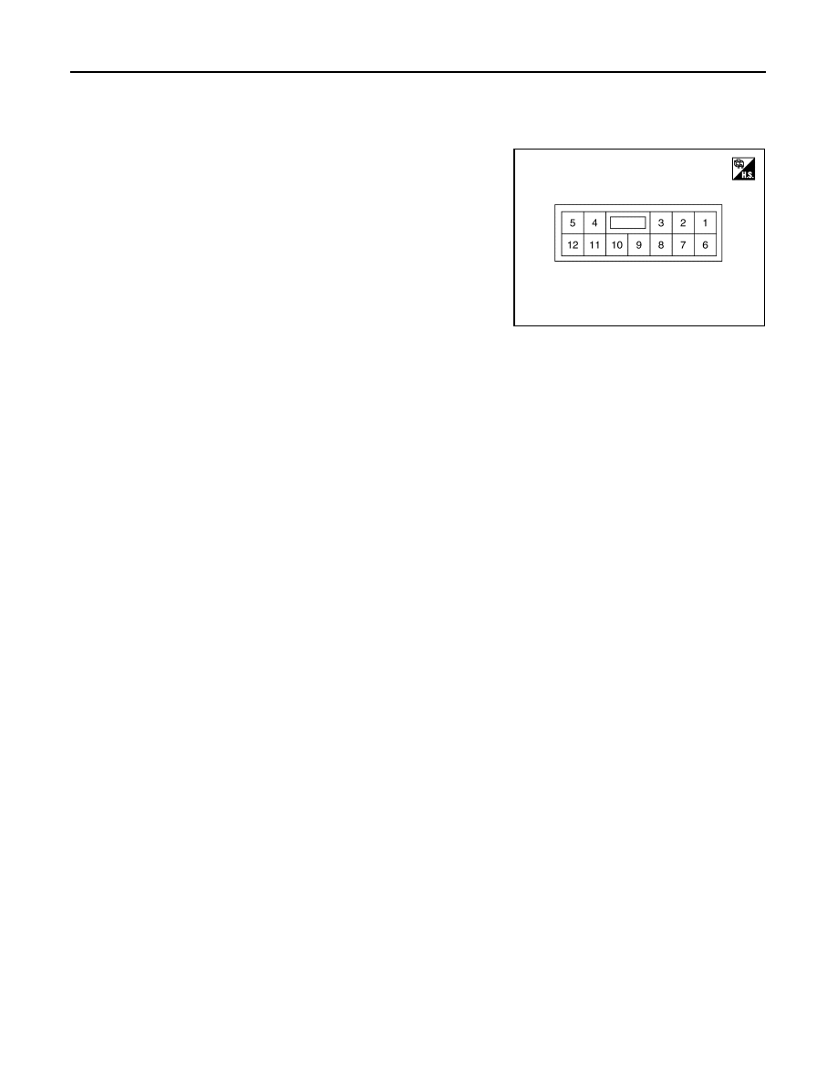
TERMINAL LAYOUT

PHYSICAL VALUES

JSOIA0648ZZ

DAS

PUMP CONTROL UNIT

DAS-55

< ECU DIAGNOSIS INFORMATION >

[DRIVER ASSISTANCE SYSTEM]

C

D

E

F

G

H

I

J

K

L

M

B

N

P

A

Terminal

(Wire color)

Description

Condition

Standard value

Reference value

(Approx.)

+

Signal name

Input/

Output

1

(SB)

Ground

Air pump power sup-
ply

Output

Ignition 

switch 

ON

Air pump operated

9.5 - 16 V

Battery voltage

Air pump not operated

0 - 0.1 V

0 V

2

(L)

Air pump ground

Ignition 

switch 

ON

0 - 0.1 V

0 V

3

(L)

Washer pump ground

0 - 0.1 V

0 V

4

(LG)

Washer pump power 
supply

Output

Ignition 

switch 

ON

Washer pump operated

0 - 0.1 V

0 V

Washer pump not operated

9.5 - 16 V

Battery voltage

5

(B)

Ground

Ignition 

switch 

ON

0 - 0.1 V

0 V

6

(V)

Communication line 
ground

Ignition 

switch 

ON

0 - 0.1 V

0 V

7

(BG)

Communication line 
(PUMP 

 CAMERA)

Output

Ignition 

switch 

ON

Input the waveform synchronized with 

the communication status.

8

(BR)

Communication line 
(CAMERA 

 PUMP)

Input

Ignition 

switch 

ON

Input the waveform synchronized with 

the communication status.

12

(P)

Ignition power supply

Input

Ignition 

switch 

ON

9.5 - 16 V

Battery voltage

PKIB5039J

PKIB5039J

DAS-56

< ECU DIAGNOSIS INFORMATION >

[DRIVER ASSISTANCE SYSTEM]

FRONT CAMERA UNIT

FRONT CAMERA UNIT

Reference Value

INFOID:0000000010499271

VALUE ON THE DIAGNOSIS TOOL

Monitor item

Condition

Value/Status

CAMERA HIGH TEMP

When the temperature around lane camera unit is adequate

Normal

when the temperate around the lane camera unit is high

High

TURN SIGNAL

Turn signal lamp LH and RH blinking

LH&RH

Turn signal lamp LH blinking

LH

Turn signal lamp RH blinking

RH

Turn signal lamps OFF

Off

WIPER SIGNAL

Wiper position is High

HI

Wiper position is Low

LO

Wiper position is OFF

OFF

VEHICLE SPEED

While drive

km/h

DRIVER ASSIST SYSTEM SET

When no operation in setting display on combination meter

NO REQ

When FCW Off is selected in setting display on combination meter

FCW Off

When FCW On is selected in setting display on combination meter

FCW On

When LDW Off is selected in setting display on combination meter

LDW Off

When LDW On is selected in setting display on combination meter

LDW On

When BSW Off is selected in setting display on combination meter

BSW Off

When BSW On is selected in setting display on combination meter

BSW On

When TSR Off is selected in setting display on combination meter

TSR Off

When TSR On is selected in setting display on combination meter

TSR On

When FEB Off is selected in setting display on combination meter

FEB Off

When FEB On is selected in setting display on combination meter

FEB On

BRAKE OPERATION STATUS

When brake pedal is depressed

Off

When brake pedal is pressed

On

When brake pedal is pressed

CFNRM

When brake pedal operation is not judged

UNKWN

AIMING DONE

Camera aiming is completed

finished

Camera aiming is not adjusted

not finished

AIMING RESULT

Camera aiming is completed

OK

Camera aiming is not completed

NOK

STEERING ANGLE

When driving straight

±

 3.0 deg

YAW RATE

Vehicle stopped

±

 3.0 deg/s

FCTRY AIM YAW

Camera aiming is completed

±

 3.0 deg

FCTRY AIM ROL

Camera aiming is completed

±

 3.0 deg

FCTRY AIM PIT

Camera aiming is completed

±

 3.0 deg

FEB OPERATION DISP

No display

0

Forward object is displayed

1

Approach warning is displayed

2

Collision warning is displayed

3

DAS

FRONT CAMERA UNIT

DAS-57

< ECU DIAGNOSIS INFORMATION >

[DRIVER ASSISTANCE SYSTEM]

C

D

E

F

G

H

I

J

K

L

M

B

N

P

A

BSW LEFT DISP

BSW is not operated for left side

0

BSW is operated for left side

1

BSW RIGHT DISP

BSW is not operated for right side

0

BSW is operated for right side

1

FCW STATUS DISPLAY

NOTE:
The item is indicated, but not monitored

0

1

2

3

BSW STATUS DISPLAY

BSW is OFF

0

BSW is ON

1

BSW indicator is flashing

2

BSW is malfunctioning

3

FEB STATUS DISPLAY

FEB is OFF

0

FEB is ON

1

FEB indicator is flashing

2

FEB is malfunctioning

3

FCW BUZZER

NOTE:
The item is indicated, but not monitored

0

2

FCW SETTING DISPLAY

NOTE:
The item is indicated, but not monitored

0

1

2

BSW SETTING DISPLAY

Nothing

0

BSW is OFF

1

BSW is ON

2

MOD SETTING DISPLAY

Nothing

0

MOD is OFF

1

MOD is ON

2

FEB SETTING DISPLAY

Nothing

0

FEB is OFF

1

FEB is ON

2

DAA SETTING DISPLAY

Nothing

0

DAA is OFF

1

DAA is ON

2

BSW IND BRIGHT DISP

NOTE:
The item is indicated, but not monitored

0

1

2

3

CLN RR CAMERA MSG

No display

0

Rear camera clean message is displayed

1

FCW MALFUNCTION MSG

NOTE:
The item is indicated, but not monitored

0

1

Monitor item

Condition

Value/Status


Content   ..  2158  2159  2160  2161   ..