Content .. 2156 2157 2158 2159 ..
Nissan Qashqai J11. Manual - part 2158
DAS-46
< ECU DIAGNOSIS INFORMATION >
[DRIVER ASSISTANCE SYSTEM]
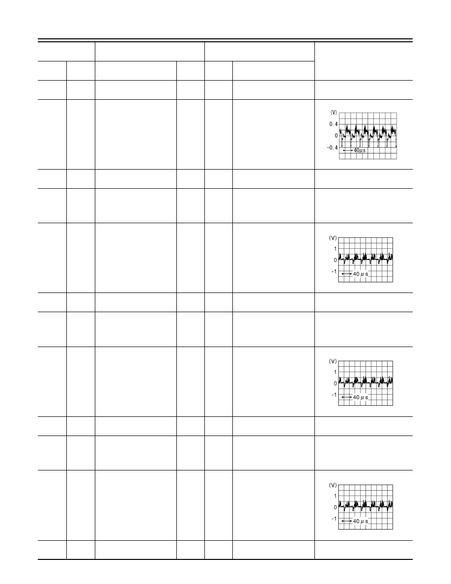
AROUND VIEW MONITOR CONTROL UNIT
23
(Shield)
—
Camera image signal
shield
—
—
—
—
24
(G)
Ground
Camera image signal
Output
ON
When camera image dis-
play
25
(B)
Ground
Rear camera ground
—
ON
—
0 V
26
(R)
Ground
Rear camera power supply
Output
ON
CAMERA selected
or
Shift selector in R (reverse)
position.
6.0 V
28
(W)
27
(Shield)
Rear camera image signal
Input
ON
CAMERA selected
or
Shift selector in R (reverse)
position.
29
(Y)
Ground
Side camera (driver side)
ground
—
ON
—
0 V
30
(L)
Ground
Side camera (driver side)
power supply
Output
ON
CAMERA selected
or
Shift selector in R (reverse)
position.
6.0 V
32
(G)
31
(Shield)
Side camera (driver side)
image signal
Input
ON
CAMERA selected
or
Shift selector in R (reverse)
position.
33
(L)
Ground
Side camera (passenger
side) ground
—
ON
—
0 V
34
(B)
Ground
Side camera (passenger
side) power supply
Output
ON
CAMERA selected
or
Shift selector in R (reverse)
position.
6.0 V
36
(Y)
35
(Shield)
Side camera (passenger
side) image signal
Input
ON
CAMERA selected
or
Shift selector in R (reverse)
position.
37
(V)
Ground
Front camera ground
—
ON
—
0 V
Terminal
(Wire color)
Description
Condition
Reference value
(Approx.)
+
–
Signal name
Input/
Output
Ignition
switch
Operation
SKIB2251J
JSNIA0834GB
JSNIA0834GB
JSNIA0834GB