Nissan Juke F15. Manual - part 787
FRONT DRIVE SHAFT
FAX-87
< REMOVAL AND INSTALLATION >
[TYPE 2]
C
E
F
G
H
I
J
K
L
M
A
B
FAX
N
O
P
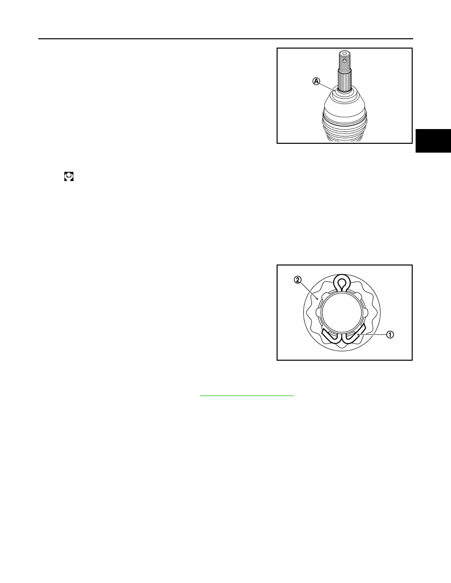
• Clean the matching surface of drive shaft and wheel hub assembly.
And then apply paste [service parts (440037S000)] to surface (A)
of joint sub-assembly of drive shaft.
CAUTION:
Apply paste to cover entire flat surface of joint sub-assembly
of drive shaft.
• Use the following torque range for tightening the wheel hub lock nut.
CAUTION:
• Since the drive shaft is assembled by press-fitting, use the tightening torque range for the wheel
hub lock nut.
• Be sure to use torque wrench to tighten the wheel hub lock nut. Never use a power tool.
• Never reuse wheel hub lock nut.
NOTE:
Wheel hub lock nut tightening torque does not over torque for avoiding axle noise, and does not less than
torque for avoiding looseness.
• Align the matching marks that have been made during removal when reusing the disc rotor.
• When installing a cotter pin (1) and adjusting cap (2), securely
bend the basal portion to prevent rattles.
CAUTION:
Never reuse cotter pin.
• Perform the final tightening of each of parts under unladen conditions, which were removed when removing
wheel hub assembly and steering knuckle.
• Perform inspection after installation. Refer to
.
2WD : Disassembly and Assembly
INFOID:0000000012201562
DISASSEMBLY
Wheel Side
1. Fix shaft with a vise.
CAUTION:
Protect shaft using aluminum or copper plates when fixing with a vise.
2. Remove boot bands, and then remove boot from joint sub-assembly.
Amount paste
: 1.0 – 3.0 g (0.04 – 0.10 oz)
JSDIA2844ZZ
: 180 – 185 N·m (18.4 – 18.8 kg-m, 133 – 136 ft-lb)
JPDIF0295ZZ