Nissan Juke F15. Manual - part 788


  Index      Nissan     Nissan Juke F15 (2015 year) - Service and Repair Manual


Search            


Content   ..  786  787  788  789   ..


Nissan Juke F15. Manual - part 788


FRONT DRIVE SHAFT

FAX-91

< REMOVAL AND INSTALLATION >

[TYPE 2]

C

E

F

G

H

I

J

K

L

M

A

B

FAX

N

O

P

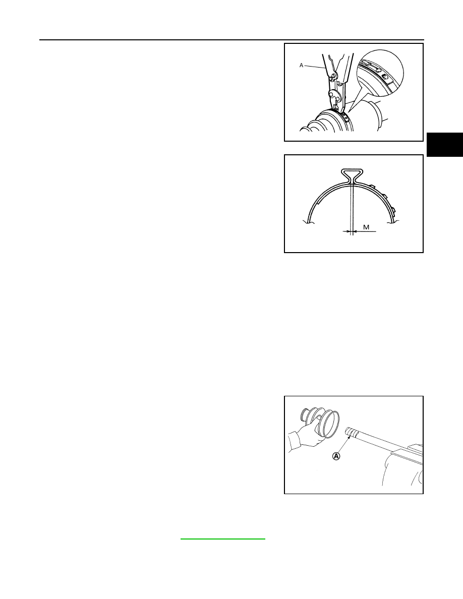
11. Secure the large and small ends of the boot with boot bands

using the boot band crimping tool (A) [SST:KV40107300 ( —

)].

CAUTION:

• Never reuse boot band.

• Secure boot band so that dimension (M) meets the speci-

fication as shown in the figure.

12. Check that displacement does not occur when boot is rotated with the joint sub-assembly and shaft fixed.

CAUTION:

• Reinstall them using boot bands when boot installation positions become incorrect.

• Never reuse boot band.

Transaxle Side (Left Drive Shaft)

1. Clean the old grease on housing assembly with paper waste.
2. Install dust shield to housing assembly.

CAUTION:

Never reuse dust shield.

3. Install circular clip to housing.

CAUTION:

Never reuse circular clip.

4. Install boot and boot bands to housing assembly.

CAUTION:

• Wrap serration on housing assembly with tape (A) to pro-

tect the boot from damage.

• Never reuse boot and boot band.

5. Remove the tape wrapped around the serration on shaft.
6. Apply NISSAN genuine grease (refer to parts catalog) to housing assembly.

JPDIF0012ZZ

Dimension (M)

: 2.0 – 3.0 mm (0.079 – 0.118 in)

DSF0047D

JSDIA2232ZZ

Grease amount

: Refer to 

FAX-109, "Drive Shaft"

.

FAX-92

< REMOVAL AND INSTALLATION >

[TYPE 2]

FRONT DRIVE SHAFT

7. Install the boot securely into grooves (indicated by “*” marks)

shown in the figure.

CAUTION:

If grease adheres to the boot mounting surface (indicated

by “*” marks) on the shaft or housing assembly, boot may

be removed. Remove all grease from the boot mounting

surface.

8. To prevent the deformation of the boot, adjust the boot installation length to the value shown below (L) by

inserting the suitable tool into the inside of boot from the large diameter side of boot and discharging

inside air.

CAUTION:

• If the boot installation length exceeds the standard, it may cause breakage of the boot.

• Be careful not to touch the inside of the boot with the tip of tool.

9. Install boot bands securely.

CAUTION:

Never reuse boot bands.

a. Put boot band in the groove on drive shaft boot. Then fit pawls

(

) into holes to temporary installation.

NOTE:

For the large diameter side, fit projection (A) and guide slit (B) at

first.

b. Pinch projection on the band with suitable pliers to tighten band.
c.

Insert the tip of band into the lower part of pawl (marked with

dotted circle) as shown in the figure.

10. Check that displacement does not occur when boot is rotated with the housing assembly fixed.

CAUTION:

• If displacement occurs, reinstall band.

• Never reuse boot band.

11. Install dynamic damper, follow the procedure described below. 
a. Install dynamic damper to shaft.

JSDIA2063ZZ

L

: Refer to 

FAX-109, "Drive Shaft"

.

JPDIF0157ZZ

JPDIF0158ZZ

FRONT DRIVE SHAFT

FAX-93

< REMOVAL AND INSTALLATION >

[TYPE 2]

C

E

F

G

H

I

J

K

L

M

A

B

FAX

N

O

P

b. Secure dynamic damper with bands in the following specified

position (A) when installing.

CAUTION:

Never reuse boot bands.

c. Install boot bands securely as showin in the figure.

12. Install boot to the wheel side. Refer to 

FAX-71, "2WD : Removal and Installation"

.

Transaxle Side (Right Drive Shaft)

1. Clean the old grease on housing assembly with paper waste.
2. Install support bearing, follow the procedure described below.
a. Install dust shield to housing.

CAUTION:

Never reuse dust shield.

b. Press support bearing (1) onto housing to using the suitable tool

(A).

CAUTION:

Never reuse support bearing.

c. Install snap ring (1).

CAUTION:

Never reuse snap ring.

A : 

Refer 

to 

FAX-109, "Drive Shaft"

.

JPDIF0178ZZ

PDIA1188J

JPDIF0056ZZ

JPDIF0106ZZ

FAX-94

< REMOVAL AND INSTALLATION >

[TYPE 2]

FRONT DRIVE SHAFT

d. Install dust shields.

CAUTION:

Never reuse dust shields.

3. Install boot and boot bands to housing assembly.

CAUTION:

• Wrap serration on housing assembly with tape (A) to pro-

tect the boot from damage.

• Never reuse boot and boot band.

4. Remove the tape wrapped around the serration on shaft.
5. Apply NISSAN genuine grease (refer to parts catalog) to housing assembly.

6. Install the boot securely into grooves (indicated by “*” marks)

shown in the figure.

CAUTION:

If grease adheres to the boot mounting surface (indicated

by “*” marks) on the shaft or housing assembly, boot may

be removed. Remove all grease from the boot mounting

surface.

7. To prevent the deformation of the boot, adjust the boot installation length to the value shown below (L) by

inserting the suitable tool into the inside of boot from the large diameter side of boot and discharging

inside air.

CAUTION:

• If the boot installation length exceeds the standard, it may cause breakage of the boot.

• Be careful not to touch the inside of the boot with the tip of tool.

8. Install boot bands securely.

CAUTION:

Never reuse boot bands.

JPDIF0127ZZ

JSDIA2232ZZ

Grease amount

: Refer to 

FAX-109, "Drive Shaft"

.

JSDIA2063ZZ

L

: Refer to 

FAX-109, "Drive Shaft"

.


Content   ..  786  787  788  789   ..