Nissan Juke F15. Manual - part 786
FRONT DRIVE SHAFT
FAX-83
< REMOVAL AND INSTALLATION >
[TYPE 2]
C
E
F
G
H
I
J
K
L
M
A
B
FAX
N
O
P
2WD : Removal and Installation
INFOID:0000000012201561
REMOVAL
Left Side
1. Remove tires with power tool. Refer to
WT-39, "Removal and Installation"
.
2. Remove wheel sensor and sensor harness. Refer to
BRC-147, "FRONT WHEEL SENSOR : Exploded
.
3. Remove lock plate from strut assembly. Refer to
BR-25, "FRONT : Removal and Installation"
.
4. Remove caliper assembly. Hang caliper assembly not to interfere with work. Refer to
CALIPER ASSEMBLY : Removal and Installation"
.
CAUTION:
Never depress brake pedal while brake caliper is removed.
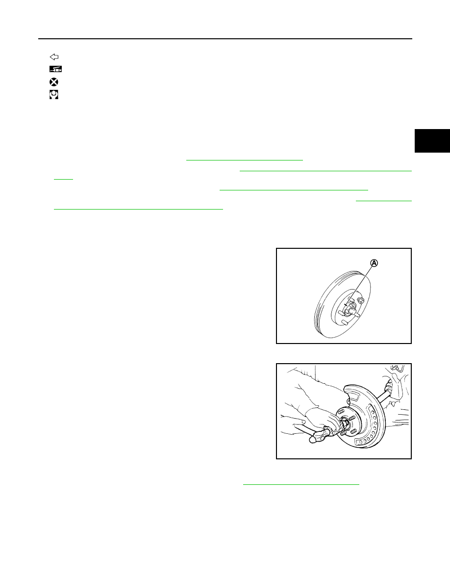
5. Remove disc rotor.
CAUTION:
• Put matching marks (A) on the wheel hub assembly and
the disc rotor before removing the disc rotor.
• Never drop disc rotor.
6. Remove cotter pin, and adjusting cap, and then loosen wheel hub lock nut with power tool.
7. Patch wheel hub lock nut with a piece of wood. Hammer the
wood to disengage wheel hub assembly from drive shaft.
NOTE:
Use suitable puller, if wheel hub assembly and drive shaft can-
not be separated even after performing the above procedure.
8. Remove wheel hub lock nut.
9. Remove strut assembly from steering knuckle. Refer to
FSU-9, "Removal and Installation"
.
10. Remove drive shaft from wheel hub assembly.
CAUTION:
• Never place drive shaft joint at an extreme angle. Also be careful not to overextend slide joint.
• Never allow drive shaft to hang down without support for joint sub-assembly, shaft and the other
parts.
13. Heat insulator
: Wheel side
: Fill NISSAN Genuine grease or equivalent.
: Always replace after every disassembly.
: N·m (kg-m, ft-lb)
JPDIG0066ZZ
JPDIG0070ZZ