Nissan Juke F15. Manual - part 784


  Index      Nissan     Nissan Juke F15 (2015 year) - Service and Repair Manual


Search            


Content   ..  782  783  784  785   ..


Nissan Juke F15. Manual - part 784


FRONT DRIVE SHAFT BOOT

FAX-75

< REMOVAL AND INSTALLATION >

[TYPE 2]

C

E

F

G

H

I

J

K

L

M

A

B

FAX

N

O

P

CAUTION:

• Since the drive shaft is assembled by press-fitting, use the tightening torque range for the wheel

hub lock nut.

• Be sure to use torque wrench to tighten the wheel hub lock nut. Never use a power tool.

• Never reuse wheel hub lock nut.

NOTE:

Wheel hub lock nut tightening torque does not over torque for avoiding axle noise, and does not less than

torque for avoiding looseness.

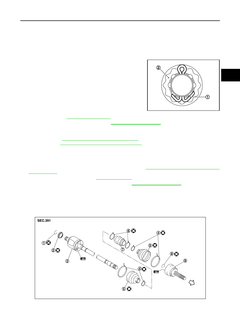
22. When installing a cotter pin (1) and adjusting cap (2), securely

bend the basal portion to prevent rattles.

CAUTION:

Never reuse cotter pin.

23. Install tires. Refer to 

WT-39, "Exploded View"

.

24. Perform inspection after installation. Refer to 

FAX-75, "2WD : Inspection"

.

Transaxle Side

• Install drive shaft to vehicle.

- Installation: Refer to 

FAX-83, "2WD : Removal and Installation"

.

- Assembly: Refer to 

FAX-87, "2WD : Disassembly and Assembly"

.

2WD : Inspection

INFOID:0000000012201556

INSPECTION AFTER INSTALLATION

1. Check wheel sensor harness for proper connection. Refer to 

BRC-147, "FRONT WHEEL SENSOR :

Exploded View"

.

2. Check the wheel alignment. Refer to 

FSU-7, "Inspection"

.

3. Adjust neutral position of steering angle sensor. Refer to 

BRC-63, "Work Procedure"

.

AWD
AWD : Exploded View

INFOID:0000000012201557

LEFT SIDE

JPDIF0295ZZ

JSDIA2093ZZ

FAX-76

< REMOVAL AND INSTALLATION >

[TYPE 2]

FRONT DRIVE SHAFT BOOT

RIGHT SIDE

AWD : Removal and Installation

INFOID:0000000012201558

REMOVAL

Wheel Side

1. Remove tires with power tool. Refer to 

WT-39, "Removal and Installation"

.

2. Remove wheel sensor and sensor harness. Refer to 

BRC-147, "FRONT WHEEL SENSOR : Exploded

View"

.

3. Remove lock plate from strut assembly. Refer to 

BR-25, "FRONT : Removal and Installation"

.

4. Remove caliper assembly. Hang caliper assembly not to interfere with work. Refer to 

BR-55, "BRAKE

CALIPER ASSEMBLY : Removal and Installation"

.

CAUTION:

Never depress brake pedal while brake caliper is removed.

5. Remove disc rotor.

CAUTION:

1.

Circular clip

2.

Dust shield

3.

Housing assembly

4.

Boot band

5.

Boot

6.

Damper band

7.

Dynamic damper

8.

Circular clip

9.

Joint sub-assembly

: Wheel side

: Fill NISSAN Genuine grease or equivalent.

: Always replace after every disassembly.

1.

Joint sub-assembly

2.

Circular clip

3.

Boot band

4.

Boot

5.

Damper band

6.

Dynamic damper

7.

Housing assembly

: Wheel side

: Fill NISSAN Genuine grease or equivalent.

: Always replace after every disassembly.

: N·m (kg-m, ft-lb)

JSDIA2095GB

FRONT DRIVE SHAFT BOOT

FAX-77

< REMOVAL AND INSTALLATION >

[TYPE 2]

C

E

F

G

H

I

J

K

L

M

A

B

FAX

N

O

P

• Put matching marks (A) on the wheel hub assembly and

the disc rotor before removing the disc rotor.

• Never drop disc rotor.

6. Remove cotter pin, and adjusting cap, and then loosen wheel hub lock nut with power tool.
7. Patch wheel hub lock nut with a piece of wood. Hammer the

wood to disengage wheel hub assembly from drive shaft.

NOTE:

Use suitable puller, if wheel hub assembly and drive shaft can-

not be separated even after performing the above procedure.

8. Remove wheel hub lock nut.
9. Remove strut assembly from steering knuckle. Refer to 

FSU-9, "Removal and Installation"

.

10. Remove drive shaft from wheel hub assembly.

CAUTION:

• Never place drive shaft joint at an extreme angle. Also be careful not to overextend slide joint.

• Never allow drive shaft to hang down without support for joint sub-assembly, shaft and the other

parts.

11. Remove boot bands, and then remove boot from joint sub-assembly.
12. Screw drive shaft puller (A) (commercial service tool) into joint

sub-assembly screw part to a length of 30 mm (1.18 in) or more.

Support drive shaft with one hand and pull out joint sub-assem-

bly from shaft.

CAUTION:

• Align drive shaft puller and drive shaft and remove them

by pulling firmly and uniformly.

• If joint sub-assembly cannot be pulled out, try after

removing drive shaft from vehicle. Refer to 

FAX-97, "AWD

: Removal and Installation"

.

13. Remove circular clip (1) from shaft.
14. Remove boot from shaft.

Transaxle Side

• Remove boot after removing drive shaft.

JPDIG0066ZZ

JPDIG0070ZZ

JPDIF0258ZZ

JPDIF0007ZZ

FAX-78

< REMOVAL AND INSTALLATION >

[TYPE 2]

FRONT DRIVE SHAFT BOOT

- Remove: Refer to 

FAX-97, "AWD : Removal and Installation"

.

- Disassembly: Refer to 

FAX-101, "AWD : Disassembly and Assembly"

.

INSTALLATION

Wheel Side

1. Clean the old grease on joint sub-assembly with paper waste.
2. Fill serration slot joint sub-assembly (1) with NISSAN genuine

grease or equivalent until the serration slot and ball groove

become full to the brim.

CAUTION:

After applying grease, use a paper waste to wipe off old

grease that has oozed out.

3. Install boot and boot bands to shaft.

CAUTION:

• Wrap serration on shaft with tape to protect the boot from damage.

• Never reuse boot and boot band.

4. Remove the tape wrapped around the serration on shaft.
5. Position the circular clip (1) on groove at the shaft edge.

CAUTION:

Never reuse circular clip.

NOTE:

Drive joint inserter is recommended when installing circular clip.

6. Align both center axles of the shaft edge and joint sub-assembly. Then assemble shaft with joint sub-

assembly holding circular clip.

7. Install joint sub-assembly (1) to shaft using plastic hammer.

CAUTION:

• Check circular clip is properly positioned on groove of the

joint sub-assembly.

• Confirm that joint sub-assembly is correctly engaged

while rotating drive shaft.

8. Apply the specified amount of grease into the boot inside from large diameter side of boot.

JPDIF0008ZZ

JPDIF0007ZZ

JPDIF0011ZZ

Grease amount

: Refer to 

FAX-109, "Drive Shaft"

.


Content   ..  782  783  784  785   ..