Nissan Juke F15. Manual - part 782
FRONT WHEEL HUB AND KNUCKLE
FAX-67
< REMOVAL AND INSTALLATION >
[TYPE 2]
C
E
F
G
H
I
J
K
L
M
A
B
FAX
N
O
P
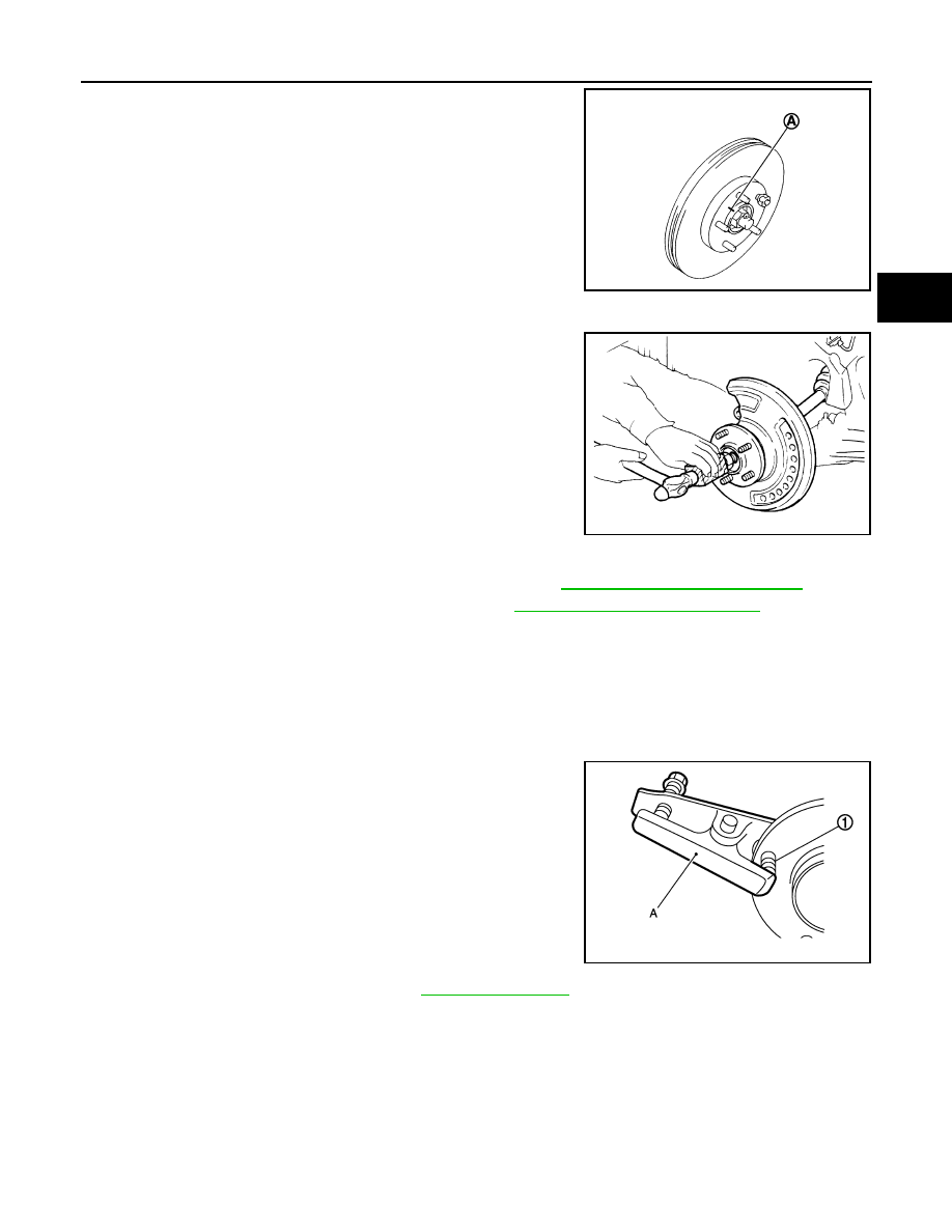
• Put matching marks (A) on the wheel hub assembly and
the disc rotor before removing the disc rotor.
• Never drop disc rotor.
6. Remove cotter pin, and adjusting cap, and then loosen wheel hub lock nut with power tool.
7. Patch wheel hub lock nut with a piece of wood. Hammer the
wood to disengage wheel hub assembly from drive shaft.
NOTE:
Use suitable puller, if wheel hub assembly and drive shaft can-
not be separated even after performing the above procedure.
8. Remove wheel hub lock nut.
9. Remove steering outer socket from steering knuckle. Refer to
ST-17, "Removal and Installation"
.
10. Remove strut assembly from steering knuckle. Refer to
FSU-9, "Removal and Installation"
.
11. Suspend the drive shaft with suitable wire.
CAUTION:
• Never place drive shaft joint at an extreme angle. Also be careful not to overextend slide joint.
• Never allow drive shaft to hang down without support for joint sub-assembly, shaft and the other
parts.
12. Remove steering knuckle from transverse link.
13. Remove wheel hub assembly and splash guard from steering knuckle.
14. Remove hub bolts (1) from wheel hub assembly, using the ball
joint remover (A) (commercial service tool).
CAUTION:
• Remove hub bolt only when necessary.
• Never hammer the hub bolt to avoid impact to the wheel
hub assembly.
• Pull out the hub bolt in a direction perpendicular to the
wheel hub assembly.
15. Perform inspection after removal. Refer to
.
INSTALLATION
Note the following, and install in the reverse order of the removal.
JPDIG0066ZZ
JPDIG0070ZZ
JPDIF0299ZZ