Nissan Juke F15. Manual - part 687


  Index      Nissan     Nissan Juke F15 (2015 year) - Service and Repair Manual


Search            


Content   ..  685  686  687  688   ..


Nissan Juke F15. Manual - part 687


EM-302

< UNIT DISASSEMBLY AND ASSEMBLY >

[MR EXCEPT FOR NISMO RS MODELS]

CYLINDER BLOCK

• If the limit is exceeded, select a connecting rod bearing according to the dimensions of the crankshaft pin

journal outer diameter, so that engine oil clearance is within the standard. Refer to 

EM-304, "Selective-fit

Service Parts"

.

Using plastigage

• Completely wipe away oil and dust on crankshaft main journal and bearing surfaces.

• Cut a piece of plastigage slightly shorter than bearing width, and place it in axial direction. Be careful not to

interfere with oil hole.

• Install the main bearing onto the cylinder block and main bearing cap, and then tighten the main bearing cap

bolts to the specified torque.

- For main bearing cap bolt tightening procedure, refer to 

EM-287, "Disassembly and Assembly"

.

CAUTION:

Never rotate crankshaft while plastigage is in place.

• Remove the main bearing cap and bearing. Measure width of the

plastigage using scale (A) printed on its bag.

NOTE:

If the limit is exceeded, follow the procedure in "Using calculation".

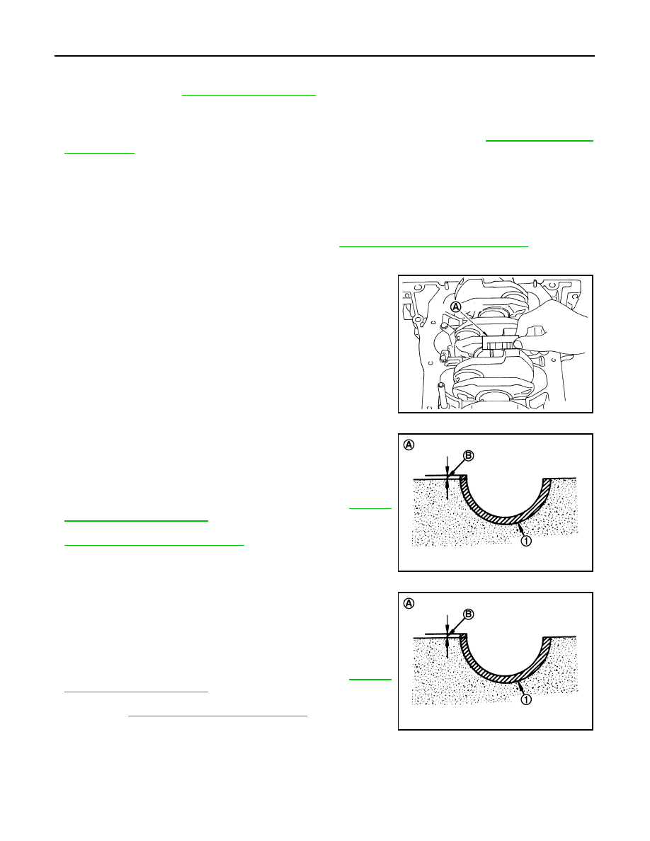
Main Bearing Crush Height

• With main bearing (1) installed, tighten main bearing cap bolt to the

specified torque. Remove main bearing cap and check that the

main bearing protrudes to [crush height (B)].

- For main bearing cap bolt tightening procedure, refer to 

EM-287,

"Disassembly and Assembly"

.

• If crush height is not secured, replace the main bearing. Refer to

EM-304, "Selective-fit Service Parts"

.

Connecting Rod Bearing Crush Height

• With connecting rod bearing (1) installed, tighten connecting rod

bolt to the specified torque. Remove connecting rod cap and check

that the front edge of the connecting rod bearing protrudes [to

crush height (B)].

- For the connecting rod bolt tightening procedure, refer to 

EM-287,

"Disassembly and Assembly"

.

• If a crush height does not exist, replace the connecting rod bear-

ing. Refer to 

EM-304, "Selective-fit Service Parts"

.

Main Bearing Cap Bolt Outer Diameter

Stan
dard

: Refer to 

EM-317, "Cylinder Block"

.

Limit

PBIC3278J

A : Image

PBIC3279J

A : Image

PBIC3279J

CYLINDER BLOCK

EM-303

< UNIT DISASSEMBLY AND ASSEMBLY >

[MR EXCEPT FOR NISMO RS MODELS]

C

D

E

F

G

H

I

J

K

L

M

A

EM

N

P

O

• Measure diameter at two locations (d1 and d2) as shown in the fig-

ure.

• If another narrower part in the threads is identified, use the position

as d2.

• Calculate the difference between d1 and d2.

• Replace main bearing cap bolts if the limit is exceeded (the differ-

ence between the dimensions is large).

Connecting Rod Bolt Outer Diameter

• Measure the outer diameter d at the position shown as in the fig-

ure.

• If another narrower part in the threads is identified, use the position

as d.

• Replace connecting rod bolts if the limit is exceeded (it is thinner).

A : d1 measurement range
B : d2 measurement range

Limit : 0.15 mm (0.0059 in)

PBIC3253J

Limit : 

φ7.75 mm (0.305 in)

PBIC3254J

EM-304

< UNIT DISASSEMBLY AND ASSEMBLY >

[MR EXCEPT FOR NISMO RS MODELS]

HOW TO SELECT PISTON AND BEARING

HOW TO SELECT PISTON AND BEARING

Selective-fit Service Parts

INFOID:0000000012197447

SELECTION METHOD

• The identification grade stamped on each part is the grade for the dimension measured in new condition. It is

not applied to reused parts.

• For reused or repaired parts, measure the dimension accurately. Determine the grade by comparing the

measurement with the values of each selection table in this section.

• For details of the measurement method of each part, the reuse standards and the selection method of the

selective fitting parts, refer to the text.

PISTON SELECTIVE-FIT SERVICE PARTS

When New Cylinder Block is Used

• Check cylinder bore grade number (either 1 or 2) stamped on cyl-

inder block LH surface (L), and select piston of the same grade

number.

• If there is a correction stamp, the symbol is the correct one.

NOTE:

Piston is a service part for piston pin and assembly.

When Reusing a Cylinder Block

1. Measure cylinder block bore inner diameter. Refer to 

EM-294, "Inspection"

.

Position

Selective-fit service parts

Item to be selected

Selection method

Between cylinder block 
and 
crankshaft

Main bearing

Main bearing grade
(Bearing thickness)

Select proper size according to cylinder 
block main bearing housing grade 
(housing inner diameter) and crankshaft 
main journal grade (journal outer diam-
eter).

Between crankshaft 
and
connecting rod

Connecting rod bearing

Connecting rod bearing grade
(Bearing thickness)

Select proper size according to con-
necting rod large end grade (connecting 
rod large end inner diameter) and 
crankshaft pin journal grade (pin outer 
diameter).

Between cylinder block 
and
piston

Piston and piston pin as-
sembly
Note: Piston and piston pin 
are service parts for assem-
bly.

Piston grade
(Piston outer diameter)

Piston grade = cylinder bore grade 
(bore inner diameter)

A

: Correction stamp

B

: Standard stamp

C

: Cylinder No. 1 bore grade

D

: Cylinder No. 2 bore grade

E

: Cylinder No. 3 bore grade

F

: Cylinder No. 4 bore grade

G

: No. 1 main bearing housing grade

H

: No. 2 main bearing housing grade

I

: No. 3 main bearing housing grade

J

: No. 4 main bearing housing grade

K

: No. 5 main bearing housing grade

: Engine front

PBIC3264J

HOW TO SELECT PISTON AND BEARING

EM-305

< UNIT DISASSEMBLY AND ASSEMBLY >

[MR EXCEPT FOR NISMO RS MODELS]

C

D

E

F

G

H

I

J

K

L

M

A

EM

N

P

O

2. Determine the grade number of the measured cylinder bore at

"Cylinder Bore Inner Diameter" in the Selective-fit Service Parts

Table, and select the piston of the same grade number.

Selective-fit Service Parts Table

Unit: mm (in)

*: No stamp is only for piston side.

SELECTIVE-FIT CONNECTING ROD BEARING

Using New Connecting Rod and Crankshaft

1. Find the large end grade (D) of connecting rod side surface in

the rows of the Selective-fit Service Parts Table.

NOTE:

The symbol of connecting rod is one example.

2. Find the pin diameter grade of crankshaft front surface in the

columns of the Selective-fit Service Parts Table.

3. Find the symbol at the intersection of the selected row and column in the Selective-Fit fervice Parts Table.
4. Find the symbol at the intersection in "Connecting rod bearing grade table", and select it.

When Reusing Crankshaft and Connecting Rod

1. Measure each dimension of connecting rod large end inner diameter and crankshaft pin outer diameter.
2. Find the measured dimension in the Selective-fit Service Parts Table.
3. The procedure below is the same procedure as step 3 and later steps of "Using new connecting rod and

crankshaft".

A

: Top surface identifica-
tion mark

B

: Front mark

C

: Piston grade

JSBIA5774ZZ

Grade number (stamping)

1

2 (or no stamp*)

Cylinder bore inner diameter

79.700 – 79.710 (3.1378 – 3.1382)

79.710 – 79.720 (3.1382 – 3.1386)

Piston outer diameter

79.670 – 79.680 (3.1366 – 3.1370)

79.680 – 79.690 (3.1370 – 3.1374)

A

: Oil hole

B

: Management code

C

: Cylinder No.

D

: Large end grade

E

: Front mark

JPBIA4442ZZ

A

: No. 1 pin journal grade

B

: No. 2 pin journal grade

C

: No. 3 pin journal grade

D

: No. 4 pin journal grade

E

: No. 1 main journal grade

F

: No. 2 main journal grade

G : No. 3 main journal grade
H

: No. 4 main journal grade

I

: No. 5 main journal grade

PBIC3261J


Content   ..  685  686  687  688   ..