Nissan Juke F15. Manual - part 685
EM-294
< UNIT DISASSEMBLY AND ASSEMBLY >
[MR EXCEPT FOR NISMO RS MODELS]
CYLINDER BLOCK
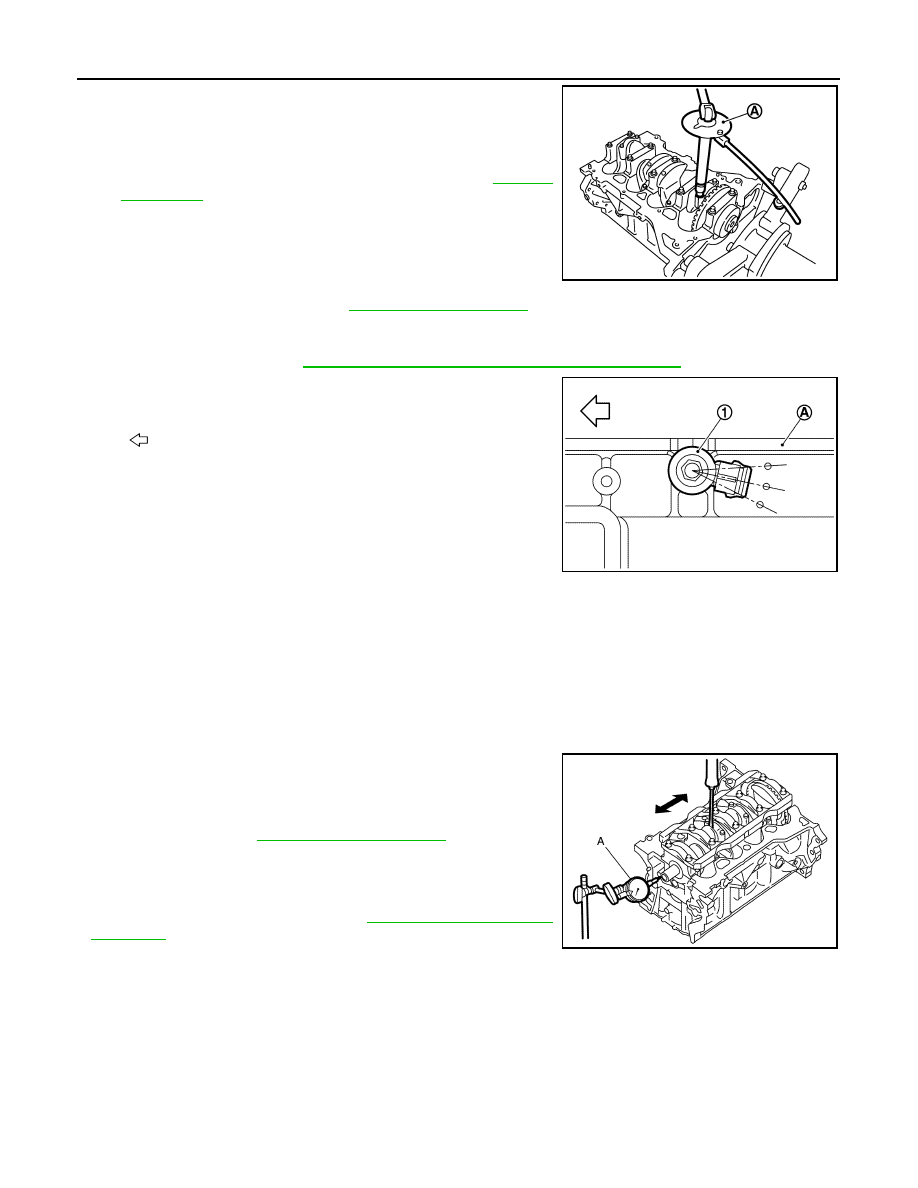
Check tightening angle with an angle wrench [SST:
KV10112100 (BT8653-A)] A or a protractor. Never estimate
tightening angle visually.
• Check that the crankshaft rotates smoothly by hand after tight-
ening the main bearing cap bolt.
• Check the connecting rod side clearance. Refer to
.
14. Install the oil pan (upper). Refer to
NOTE:
Install the rear oil seal after installing the oil pan (upper).
15. Install rear oil seal. Refer to
EM-271, "REAR OIL SEAL : Removal and Installation"
16. Install knock sensor (1) in the direction shown in the figure.
CAUTION:
• Never subject parts to impact. If any impact is applied,
replace it.
• Check that no foreign material adheres to cylinder block
and knock sensor mounting surfaces.
• Install connectors so that they are positioned toward
engine rear.
• Be sure to use specified bolts.
• Never hold connector while tightening bolts.
• Never allow installed sensor connector to interfere with other parts.
17. Assemble in the reverse order of disassembly.
Inspection
INFOID:0000000012197446
INSPECTION AFTER DISASSEMBLY
Crankshaft Side Clearance
• Move crankshaft to front or rear, and measure thrust bearing-to-
crank arm clearance using a dial indicator (A).
• If the limit is exceeded, replace the thrust bearing and then mea-
sure again. Replace the crankshaft if it still exceeds the limit.
- When replacing the crankshaft, refer to
and select the main bearing and connecting rod bear-
ing.
Connecting Rod Side Clearance
PBIC3245J
A
: Left side of cylinder block
: Engine front
JPBIA5163ZZ
Stan
dard
: Refer to
Limit
JPBIA4436ZZ