Nissan Juke F15. Manual - part 686


  Index      Nissan     Nissan Juke F15 (2015 year) - Service and Repair Manual


Search            


Content   ..  684  685  686  687   ..


Nissan Juke F15. Manual - part 686


EM-298

< UNIT DISASSEMBLY AND ASSEMBLY >

[MR EXCEPT FOR NISMO RS MODELS]

CYLINDER BLOCK

NOTE:

Piston and piston pin are service parts for assembly.

- When replacing the connecting rod, refer to 

EM-304, "Selective-fit Service Parts"

 and select the connecting

rod bearing.

Cylinder Block Upper Surface Distortion

• Remove old gasket on cylinder block upper surface using a scraper. Also remove oil, scale, and carbon

deposits.

CAUTION:

Never allow gasket fragments to enter oil or engine coolant passages.

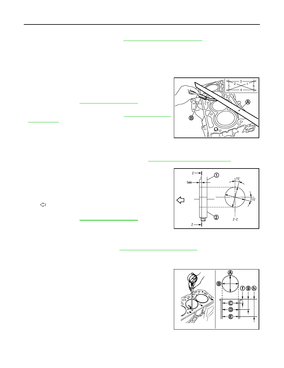
• Check flatness of cylinder block upper surface using a straight-

edge (A) and a feeler gauge (B). Measure distortion, at several

points each in six directions.

• If the limit is exceeded, replace the cylinder block.

- When replacing the cylinder block, refer to 

EM-304, "Selective-fit

Service Parts"

 and select the main bearing.

Main Bearing Housing Inner Diameter

• Without installing main bearing, install main bearing cap, and tighten main bearing cap bolts to the specified

torque.

- For main bearing cap bolt tightening procedure, refer to 

EM-287, "Disassembly and Assembly"

.

• Measure the main bearing housing inside diameter with a bore gauge.

• Measure the position shown in the figure (5 mm rearward from

main bearing housing front side end surface) in two directions, as

shown in the figure. Use the smaller one as the measured value.

• If the result is outside the standard, replace the cylinder block.

NOTE:

Main bearing cap is machined together with cylinder block, so they cannot be replaced separately.

- When replacing the cylinder block, refer to 

EM-304, "Selective-fit Service Parts"

 and select the main bearing.

Piston-to-cylinder Bore Clearance

Cylinder bore inner diameter

• Use a bore gauge and measure at three points from the top of the

engine (upper, middle, lower: “C”, “D”, and “E” as shown in the fig-

ure) in two directions (“A”, “B”) for measurement at a total of six

points.

NOTE:

The measurement point for bore grade is 60 mm below the cylin-

der head mounting surface (position “D” in the figure). Measure the

dimension in the engine LH/RH directions (“B” in the figure).

Limit : Refer to 

EM-317, "Cylinder Block"

.

PBIC3250J

1

: Cylinder block

2

: Main bearing cap

: Engine front

Stan
dard

: Refer to 

EM-317, "Cylinder Block"

.

PBIC3271J

f

: 10 mm (0.39 in)

g

: 60 mm (2.36 in)

h

: 130 mm (5.12 in) 

JPBIA2059ZZ

CYLINDER BLOCK

EM-299

< UNIT DISASSEMBLY AND ASSEMBLY >

[MR EXCEPT FOR NISMO RS MODELS]

C

D

E

F

G

H

I

J

K

L

M

A

EM

N

P

O

• Replace the cylinder block if the limit is exceeded, or if damage or seizure is found on cylinder inner wall.

NOTE:

There is no service setting for oversized piston

- When replacing the cylinder block, refer to 

EM-304, "Selective-fit Service Parts"

 and select the main bearing.

Piston outer diameter

• Measure piston skirt outer diameter using a micrometer (A).

How to calculate piston-to-cylinder bore clearance

• Calculate from the piston skirt outer diameter and the cylinder bore

inner diameter (measured at position “D” in direction “B”).

(Clearance) = (Cylinder bore inner diameter) - (Piston skirt outer

diameter)

• If the limit is exceeded, refer to the standard for each part standard, and replace the connecting rod and/or

the piston and piston pin assembly.

- When replacing piston and piston assembly, refer to 

EM-304, "Selective-fit Service Parts"

 and select the cor-

rect parts.

NOTE:

Piston and piston pin are service parts for assembly.

- When replacing the cylinder block, refer to 

EM-304, "Selective-fit Service Parts"

 and select the main bearing.

Crankshaft Main Journal Diameter

Cylinder bore inner diameter standard

: Refer to 

EM-317, "Cylinder Block"

.

Out-of-round limit (difference between measure-
ments X and Y)
Taper limit (difference between measurements A and 
C)

: Refer to 

EM-317, "Cylinder Block"

.

Stan-
dard

: Refer to 

EM-317, "Cylinder Block"

.

PBIC3272J

f

: 10 mm (0.39 in)

g

: 60 mm (2.36 in)

h

: 130 mm (5.12 in) 

Stan
dard

: Refer to 

EM-317, "Cylinder Block"

.

Limit

JPBIA2059ZZ

EM-300

< UNIT DISASSEMBLY AND ASSEMBLY >

[MR EXCEPT FOR NISMO RS MODELS]

CYLINDER BLOCK

• Measure the main journal outer diameter using a micrometer (A).

• If it is outside the standard, check the main bearing oil clearance

and use the undersize bearing. Refer to "Main bearing oil clear-

ance."

Crankshaft Pin Journal Diameter

• Measure the main journal outer diameter using a micrometer.

• If it is outside the standard, check the connecting rod bearing oil clearance and use the undersize bearing.

Refer to "Connecting rod bearing oil clearance."

Out-of-round and Taper of Crankshaft

• Measure each main journal and pin journal at four locations shown

in the figure using a micrometer.

• Out-of-round is indicated by the difference between the dimen-

sions at positions “A” and “B” measured in directions “X” and “Y”.

• Taper is indicated by the difference between the dimensions in

directions “X” and “Y” measured at positions “A” and “B”.

• Correct or replace the crankshaft if it exceeds the limit.

- If repair is performed, check the oil clearance and select the main

bearing and connecting rod bearing. Refer to "Main bearing oil

clearance" or "Connecting rod bearing oil clearance."

- When replacing the crankshaft, refer to 

EM-304, "Selective-fit Service Parts"

 and select the main bearing

and connecting rod bearing.

Crankshaft Runout

• Set a pair of V-blocks on a level block and support journals at both ends of crankshaft.

• Set a dial indicator (A) vertically onto journal No. 3.

• Rotate crankshaft one rotation and read indication on the indicator.

• Replace crankshaft if the limit is exceeded.

- When replacing the crankshaft, refer to 

EM-304, "Selective-fit Ser-

vice Parts"

 and select the main bearing and connecting rod bear-

ing.

Connecting Rod Bearing Oil Clearance

Using calculation

Stan
dard

: Refer to 

EM-317, "Cylinder Block"

.

PBIC3457J

Stan
dard

: Refer to 

EM-317, "Cylinder Block"

.

Limit

: Refer to 

EM-317, "Cylinder Block"

.

PBIC3459J

Stan
dard

: Refer to 

EM-317, "Cylinder Block"

.

Limit

PBIC3458J

CYLINDER BLOCK

EM-301

< UNIT DISASSEMBLY AND ASSEMBLY >

[MR EXCEPT FOR NISMO RS MODELS]

C

D

E

F

G

H

I

J

K

L

M

A

EM

N

P

O

• Install connecting rod bearing (2) onto connecting rod (3) and con-

necting rod cap (1). Tighten connecting rod bolts to the specified

torque. Using an inside micrometer, measure connecting rod inner

diameter.

- For the connecting rod bolt tightening procedure, refer to 

EM-287,

"Disassembly and Assembly"

.

• Measure crankshaft pin journal diameter. Refer to "Crankshaft pin

journal diameter."

• (Oil clearance) = (Connecting rod bearing inner diameter) - (Camshaft pin journal outer diameter)

• If the limit is exceeded, select a connecting rod bearing according to the dimensions of the crankshaft pin

journal outer diameter, so that engine oil clearance is within the standard. Refer to 

EM-304, "Selective-fit

Service Parts"

.

Using plastigage

• Completely wipe away oil and dust on crankshaft pin journal and bearing surfaces.

• Cut a piece of plastigage slightly shorter than bearing width, and place it in axial direction. Be careful not to

interfere with oil hole.

• Install connecting rod bearing to connecting rod and connecting rod cap. Tighten connecting rod bolts to the

specified torque.

- For the connecting rod bolt tightening procedure, refer to 

EM-287, "Disassembly and Assembly"

.

CAUTION:

Never rotate crankshaft while plastigage is in place.

• Remove connecting rod cap and bearing. Measure width of the

plastigage using scale (A) printed on its bag.

NOTE:

If the limit is exceeded, follow the procedure in "Using calculation".

Main Bearing Oil Clearance

Using calculation

• Install main bearing (3) onto cylinder block (1) and main bearing

cap (2). Tighten main bearing cap bolts to the specified torque.

Using a bore gauge, measure main bearing inner diameter.

- For main bearing cap bolt tightening procedure, refer to 

EM-287,

"Disassembly and Assembly"

.

• Measure crankshaft main journal diameter. Refer to "Crankshaft

main journal diameter."

• (Oil clearance) = (Connecting rod bearing inner diameter) - (Cam-

shaft main journal outer diameter)

A :  Image

B

: Inner diameter 
measurement di-
rection

Stan
dard

: Refer to 

EM-317, "Cylinder Block"

.

Limit

PBIC3275J

JPBIA4438ZZ

A :  Image

B

: Inner diameter measure-
ment direction

PBIC3277J


Content   ..  684  685  686  687   ..