Nissan Juke F15. Manual - part 616


  Index      Nissan     Nissan Juke F15 (2015 year) - Service and Repair Manual


Search            


Content   ..  614  615  616  617   ..


Nissan Juke F15. Manual - part 616


EM-18

< SYMPTOM DIAGNOSIS >

[MR FOR NISMO RS MODELS]

NOISE, VIBRATION AND HARSHNESS (NVH) TROUBLESHOOTING

SYMPTOM DIAGNOSIS

NOISE, VIBRATION AND HARSHNESS (NVH) TROUBLESHOOTING

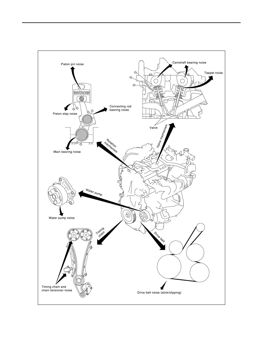
NVH troubleshooting Chart

INFOID:0000000012197239

1. Locate the area where noise occurs.
2. Confirm the type of noise.
3. Specify the operating condition of engine.

JPBIA4301GB

NOISE, VIBRATION AND HARSHNESS (NVH) TROUBLESHOOTING

EM-19

< SYMPTOM DIAGNOSIS >

[MR FOR NISMO RS MODELS]

C

D

E

F

G

H

I

J

K

L

M

A

EM

N

P

O

4. Check specified noise source.
If necessary, repair or replace these parts.

A: Closely related B: Related C: Sometimes related —: Not related

Location 

of noise

Type of 

noise

Operating condition of engine

Source of 

noise

Check item

Refer-

ence page

Before 

warm-

up

After 

warm-

up

When 

start-

ing

When 

idling

When 

racing

While 

driving

Top of en-
gine
Rocker 
cover
Cylinder 
head

Ticking or 
clicking

C

A

A

B

Tappet 
noise

Valve clearance

EM-14

Rattle

C

A

A

B

C

Camshaft 
bearing 
noise

Camshaft journal oil 
clearance
Camshaft runout

EM-140

Crank-
shaft pul-
ley
Cylinder 
block 
(Side of 
engine)
Oil pan

Slap or 
knock

A

B

B

Piston pin 
noise

Piston to piston pin oil 
clearance
Connecting rod bushing 
oil clearance

EM-144

Slap or 
rap

A

B

B

A

Piston 
slap noise

Piston to cylinder bore 
clearance
Piston ring side clear-
ance
Piston ring end gap
Connecting rod bend 
and torsion

EM-144

Knock

A

B

C

B

B

B

Connect-
ing rod 
bearing 
noise

Connecting rod bushing 
oil clearance 
Connecting rod bearing 
oil clearance

EM-144
EM-148

Knock

A

B

A

B

C

Main bear-
ing noise

Main bearing oil clear-
ance
Crankshaft runout

EM-148
EM-144

Front of 
engine
Front cov-
er

Tapping or 
ticking

A

A

B

B

B

Timing 
chain and 
chain ten-
sioner 
noise

Timing chain cracks 
and wear
Timing chain tensioner 
operation

EM-86
EM-76

Front of 
engine

Squeak-
ing or fizz-
ing

A

B

B

C

Drive belt 
(Sticking 
or slip-
ping)

Drive belt deflection

EM-20

Creaking

A

B

A

B

A

B

Drive belt 
(Slipping)

Idler pulley bearing op-
eration

Squall
Creak

A

B

B

A

B

Water 
pump 
noise

Water pump operation

CO-21

EM-20

< PERIODIC MAINTENANCE >

[MR FOR NISMO RS MODELS]

DRIVE BELT

PERIODIC MAINTENANCE

DRIVE BELT

Exploded View

INFOID:0000000012197240

Removal and Installation

INFOID:0000000012197241

REMOVAL

1. Turn the steering wheel to the right.
2. Remove the front fender protector (RH) front side bolts and clips. And keep a service area. Refer to 

EXT-

31, "Exploded View"

.

3. Hold the hexagonal part (A) of drive belt auto-tensioner (1) with

a wrench securely. Then move the wrench handle in the direc-

tion of arrow (loosening direction of tensioner).

CAUTION:

Avoid placing hand in a location where pinching may occur

if the holding tool accidentally comes off.

4. Insert a rod approximately 6 mm (0.24 in) in diameter such as

short-length screwdriver into the hole (B) of the retaining boss to

fix drive belt auto-tensioner.

• Keep drive belt auto-tensioner pulley arm locked after drive

belt is removed.

5. Remove drive belt.

INSTALLATION

1. Install drive belt.

CAUTION:

• Confirm drive belt is completely set to pulleys.

• Check for engine oil, working fluid and engine coolant are not adhered to drive belt and each

pulley groove.

2. Release drive belt auto-tensioner, and apply tension to drive belt.
3. Turn crankshaft pulley clockwise several times to equalize tension between each pulley.
4. Confirm tension of drive belt at indicator (notch on fixed side) is within the possible use range. Refer to

EM-20, "Exploded View"

.

1.

Alternator

2.

Drive belt auto-tensioner

3.

Crankshaft pulley

4.

A/C compressor 

5.

Water pump

6.

Drive belt

A.

Possible use range

B.

Range when new drive belt is in-
stalled

C.

Indicator

JPBIA4302ZZ

JPBIA4351ZZ

DRIVE BELT

EM-21

< PERIODIC MAINTENANCE >

[MR FOR NISMO RS MODELS]

C

D

E

F

G

H

I

J

K

L

M

A

EM

N

P

O

Inspection

INFOID:0000000012197242

WARNING:

Perform this step when engine is stopped.

• Check that the indicator (C) (notch on fixed side) of drive belt auto-tensioner is within the possible use range

(A) in the figure.

NOTE:

• Check the drive belt auto-tensioner indication when the engine is cold.

• When new drive belt is installed, the indicator (notch on fixed side) should be within the range (B) in the fig-

ure.

• Visually check entire drive belt for wear, damage or cracks.

• If the indicator (notch on fixed side) is out of the possible use range or belt is damaged, replace drive belt.

Adjustment

INFOID:0000000012197243

1.

Alternator

2.

Drive belt auto-tensioner

3.

Crankshaft pulley

4.

A/C compressor 

5.

Water pump

6.

Drive belt

A.

Possible use range

B.

Range when new drive belt is in-
stalled

C.

Indicator

JPBIA4302ZZ

Refer to  

EM-139, "Drive Belt"

.


Content   ..  614  615  616  617   ..